Qflow Design
Introduction
This manual explains how to design a process using Qflow Design.
Manual organization
This manual is divided into the following sections:
Quick guide: this section explains how to design a simple process using an example, so the reader can become familiar with the most basic concepts and the way the tool’s most important operations work.
User interface operation: this section gives a detailed explanation of how the user interface works. It also shows some of the most common operations and contains instructions to design a process (i.e. build the process diagram).
Process items: this section gives a detailed description of each type of process item (application data, roles and other items that are used so that processes can handle data, assign tasks, access other software systems, etc). It also includes in-depth descriptions of each item’s properties.
Process design elements: this section gives a detailed description of the elements that can be included in the design of a process: what each one is used for and its properties.
Custom forms: explains how to design forms within a process, detailing the types of components available, their properties, and how to configure their behavior and visibility according to the process step.
Quick guide
The goal of this section is to give a quick introduction to Qflow using a practical example, so the reader can start using the product and become familiar with it as soon as possible.
A simple complaints process
A business wants to improve its customer complaints handling system through a Qflow process. The complaints system they will implement is as follows:
A customer calls the business to express a complaint.
The call receiver starts a Qflow process with the following data:
Customer name
Customer e-mail address: it will be used to send them a message once the complaint is handled.
Complaint text: a description of the customer’s complaint.
Text to send to the customer: the text that will be sent to the customer in an e-mail once the complaint is handled.
The commercial manager chooses an employee as the complaint handler.
The complaint handler handles it and writes a text to send to the customer in an e-mail.
An e-mail is automatically sent to the customer, using the text from the previous step.
The process execution ends.
Building the process in Qflow
To create the template, click the “Empty BPMN template” button that is on the Qflow Design home. In the form that appears, enter the name “Complaints” and check the “Create process container subpackage” option. This way, when you save, the template will be created inside a package that will also be called “Complaints”.
When you create a process template, an initial version is automatically generated, named 1.0, whose number appears in parentheses next to the template’s name. Each version contains the process design, which is a graphical representation of how it will be executed. A process template can have several versions, but only one of them can be published, that is, the version that is used when processes are started with the template. If you decide to publish a new version, the processes that were already running will continue to use the version with which they were started.
Once the template has been created, Qflow will open the designer, where we can interact with the definition of our process. Here you can add elements to you process design. Fig. 422 shows the proposed design, which will have the following elements:
Start event: it indicates where the process execution starts. All designs must have a starting element. When a version is created, the design comes with a start event and an end event.
Select the complaint handler: it is a user task. User tasks assign tasks to users. This elements assigns the task of selecting the complaint handler to the commercial manager. When the process reaches that element, Qflow will notify the commercial manager, who will log in to Qflow Task and access the task form. There, they will be able to see the process data, select the task handler and indicate that it has finished.
Handle the complaint: it is also a user task. This task is assigned to the user that the commercial manager selected in the “Select the complaint handler” task. The complaint handler will access the task form, see the process data and input the text that will be sent to the customer.
Notify the customer: it is a mail task, which sends an e-mail to the specified address.
End event: when a process reaches an end event, its execution ends. This process only has one end event, but it is possible for a process to have several of them.
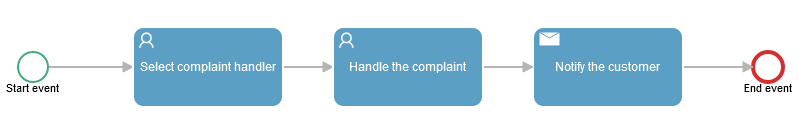
Fig. 422 Process design
Add the elements to the process design
To add the elements to the process design:
When creating the template, the process design will be shown (Fig. 423). If you do not see the process design, you can use the “Graph” option that is shown when you right-click on the template.
Fig. 423 Unmodified version design
To add the “Select the complaint handler” task, select the
 icon in the toolbar. Click on it and then click on the design. This adds the activity, although without specifying that it is a user task. When the activity is added, a column of icons appears on the right (Fig. 424). If you select the
  icon, you can quickly add another activity that will be automatically connected to the first one. Click on that icon to add another activity (this activity will be the “Handle the complaint” task). Finally, repeat the operation to add the activity that will be used to notify the customer. The design will look like Fig. 425.
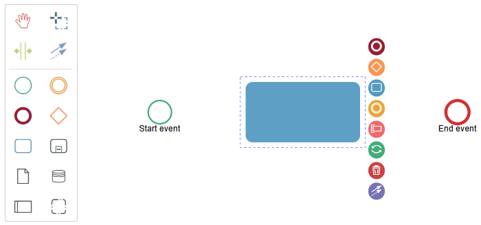
Fig. 424 Design with a recently added activity
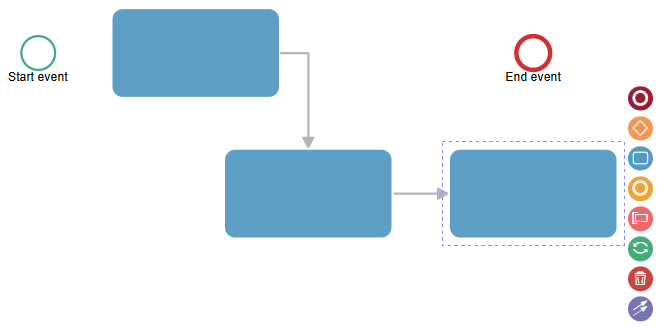
Fig. 425 The design after adding three activities to it
Select the connection tool in the toolbar (Fig. 426). Click the start event and then the first activity. This will connect both elements, indicating that the process must go from the start event to that activity.
Fig. 426 Global connect tool
Fig. 427 Create a connection from a step
Connect the last activity to the end event as well, as Fig. 428 shows.
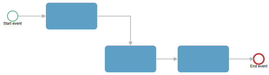
Fig. 428 The design, once the start event has been connected with the first activity, and the last activity with the end event.
The activities do not have a type yet: it is unknown whether they are user tasks, service tasks, etc. The first activity must be a user task. To specify this, select it and click the
 button. When you do this, a menu will appear to choose the activity type. Select “User task”. Repeat this procedure for the second activity. For the third one, do the same, but instead of selecting “User task”, select “Mail task”.
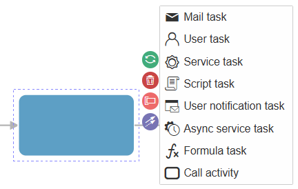
Fig. 429 Specifying an activity’s type
The design already has the steps that are needed for the process. Now you still have to specify the elements’ names and properties. For example, the first user task should have a descriptive name such as “Select complaint handler”. You should also indicate: who is the first task addressed to? Which e-mail address is the message from the mail task sent to? To be able to specify that, first you must define the items that will be referenced by those properties: to indicate who to assign a task to, a template role is required; to save the e-mail address application data is required.
For more information on how to design a process, see the Designing a process version section.
Process roles
The process requires two roles:
Commercial manager: they are the one who selects the complaint handler. A user can be assigned to this role during the process definition (the identity of the commercial manager is known). This role is the addressee of the “Select the complaint handler” task.
Complaint handler: they are the one who receives the “Handle the complaint” task. A user is assigned to this role during the process execution: it is what the commercial manager does. This role is the addressee of the “Handle the complaint” task.
To create the “Commercial manager” role:
Edit the template: click the “Edit” button in the action bar located at the top of the graph.
Now select “Roles” in the action bar. This will show a screen with the roles list, which is empty (Fig. 430).
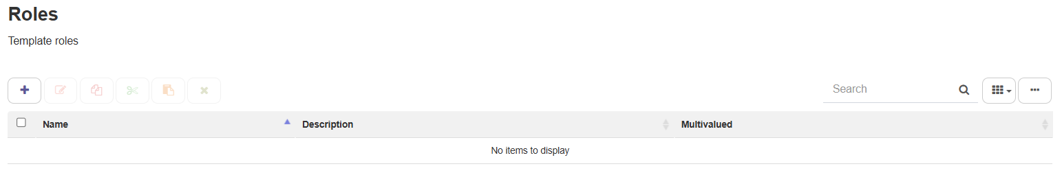
Fig. 430 Roles list
Click the button with the “+” symbol to add a role.
In the form that appears, enter the role name (Fig. 431). Then, to assign a user, use your own user account. To do this, where it says “Start typing a user…”, start typing the name of the account you are using to test Qflow. If you do not know what that name is, place the cursor over the profile picture at the top right of the screen (Fig. 432). That is the name you must enter. As you start typing, a list of users will appear. As you type, the list will show fewer elements. When you see your user account name, click it and your user account will be added as a member of the role.
Fig. 431 Role properties: the name “Commercial manager” was entered and the user “Carmen Sanjuan” is being assigned as a member

Fig. 432 Part of the screen on which the current user name is shown (“Carmen Sanjuan”, in this case)
Click the Save and add another button (
 ). This will create the role and will let you continue creating roles without closing the panel, but clearing the previous data.
Once the “Commercial manager” role has been created, create the “Complaint handler” role. It is not necessary to assign any members to it since the commercial manager will select a user to assign to that role in the “Select the complaint handler” task. In this case, since you do not need to create any other role, you may save it using the Save button. When you attempt to save the changes, Qflow will warn you that the role has no members and will ask you if you wish to continue anyway. Answer affirmatively. The role list will look like in Fig. 433.
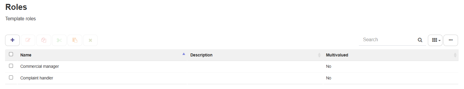
Fig. 433 Created template roles
Process application data
The necessary appplication data is:
Customer name
E-mail address
Complaint text
Text to send to the customer
To create the “Customer name” application data:
Click the “Data” button in the action bar.
Click the button with the “+” symbol to add an application datum.
Enter “Customer name” as name, “Text” as data type, which is the default option, and click the “Save and add another” button (identical to how it was done in the Role panel). This will create the datum and you will be able to add another.
Repeat step 3 for the rest of the application data (for the last one, use the Save button to save). For more information about application data, see the Application data section.
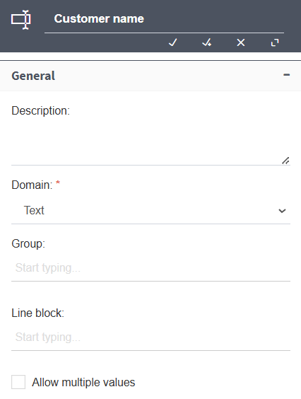
Fig. 434 Creation of the “Customer name” datum
The data list will look like in Fig. 435.
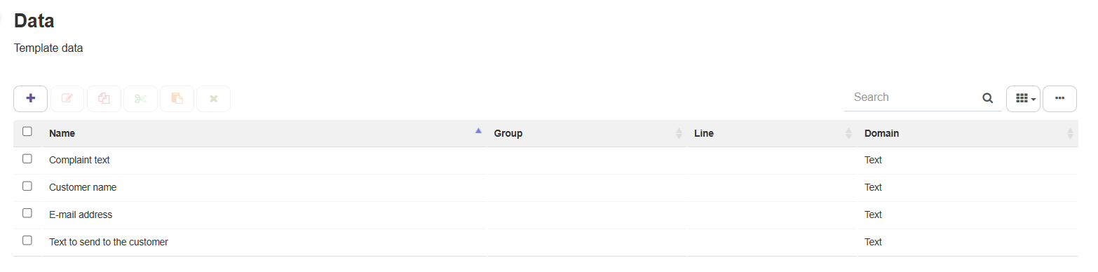
Fig. 435 Created data list
Design elements properties
Now you may configure each of the design’s elements.
Start event
To configure the start event, double-click it. The only thing you need to modify is the visibility. To do this, click on the “Form” tab to see the step’s visibility configuration.
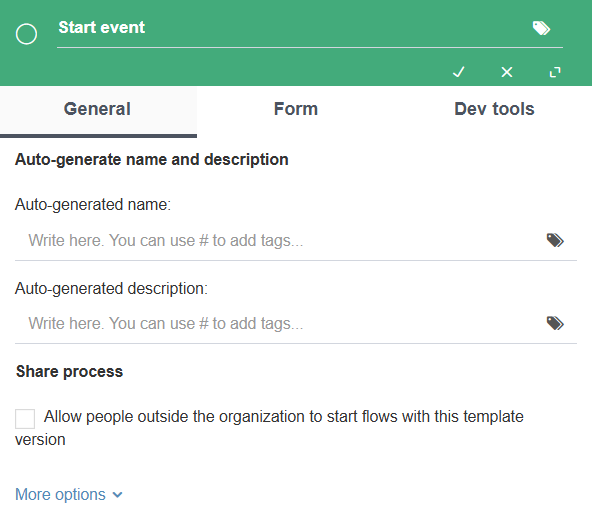
Fig. 436 Start event properties
Visibility allows you to specify which data and roles are visible and modifiable in interactive activities, such as a user task or a start event. At the beginning of the process, it is important that the user can assign values to the application data. Therefore, in the data subsection, check all the application data, clicking on the box that appears next to the column header “Data name” (Fig. 437). Then, click on the corresponding button for the “Editable” visibility ( ). In the “Visibility” column, all the data will have the “Editable” value. Click on the accept button (✓) to save the changes. For more information on visibility, go to the Data, roles, attachments, and comments visibility section.
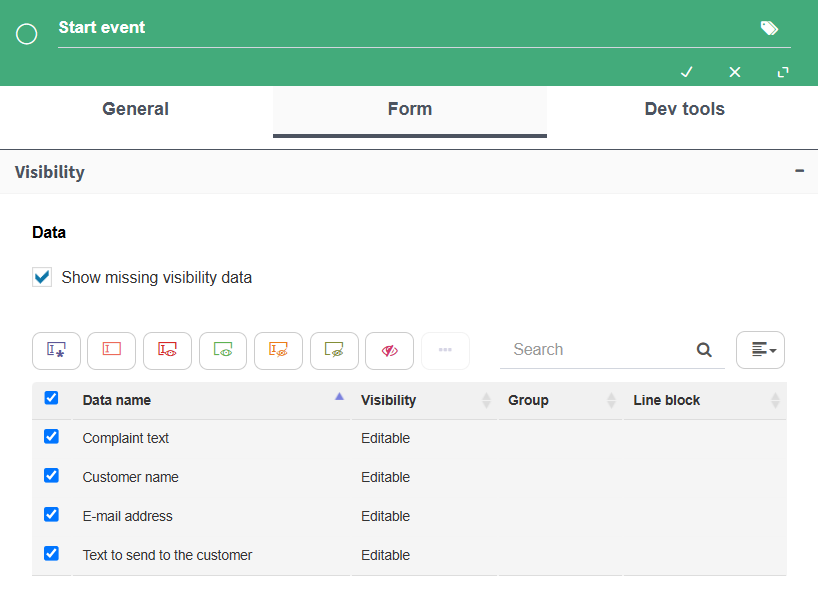
Fig. 437 Assigning the “Editable” visibility to all application data
“Select the complaint handler” task
Press the “E” key in the user task that comes immediately after the start event and write “Select the complaint handler” in the name (Fig. 438).
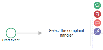
Fig. 438 Task name change
Next, double-click the task to open its configuration (Fig. 439).
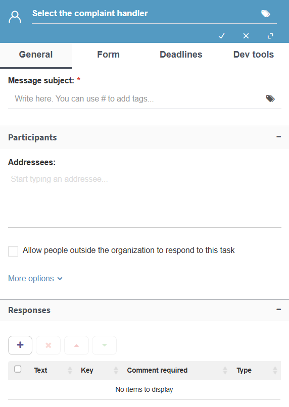
Fig. 439 User task general configuration
The first property within the general task configuration is the task subject (when e-mail is used to notify a user that they have a task, the e-mail message subject is the one entered in this property). Write “Select complaint handler for ”. The “for” at the end (followed by a space) is because we are going to include the customer name in the subject. The customer name is not available at the time of designing the process, but during its execution it will be in the “Customer name” data. It can be included in the subject using a tag (see Tags). A tag allows you to take the value of some process item and use it in some element property.
The properties for which tags can be used are indicated with an icon that represents a tag (Fig. 440).
To specify a tag, after the text you wrote in the subject, write the “#” symbol, which means that a tag will be used. Qflow shows the items that can be selected as a tag (Fig. 440).
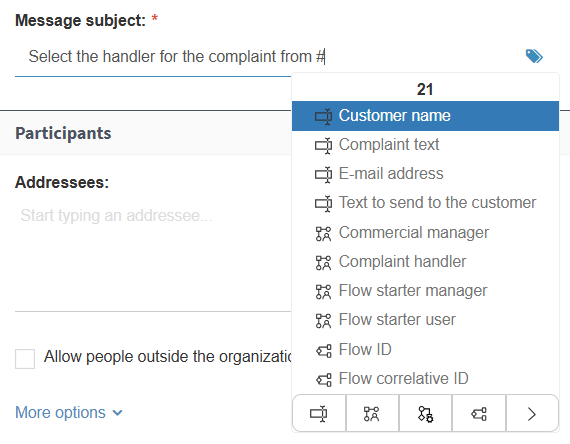
Fig. 440 Inserting a tag in the subject
Select the “Customer name” application datum from the list. In that moment, Qflow adds the tag to the subject. The tag is represented by a text with special symbols that indicate that said text is a tag, a text that indicates what item type is being used (in this case, “Data”, which means application data) and the item name (“Customer name”). See Fig. 441.
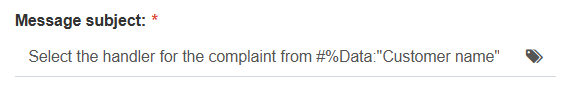
Fig. 441 Task subject with tag
Under the task subject the possible responses for the task must be entered. When a user is assigned a task, they must log in to Qflow Task to respond to it. Some tasks have various possible responses. For example, a process task could be “Do you approve of this expenditure?” and that task would have two responses, “Approve“ and “Reject”. In this case, only an answer that indicates that the complaint handler has been selected is necessary and the process can continue.
To add a response, click the button with the “+” symbol that appears underneath “Responses”. This makes Qflow add a response to the response list, which was empty. The added response has “Response 1” as its default text (Fig. 442).
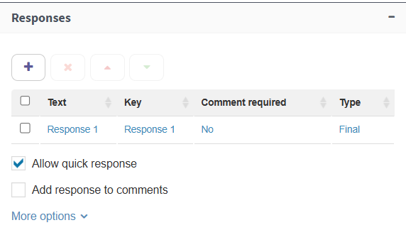
Fig. 442 Add response
Click on “Response 1”. This will let you modify the text, as Fig. 443 shows.
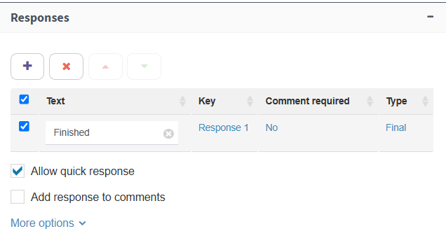
Fig. 443 Editing response
Write “Finished” and press the “Enter” key. In the response row there is a Type column whose selected option is “Final”. Do not change it; this indicates that, once a response is selected, the process must continue and go to the next element in the design (the different task response types are explained in more detail in the “Responses” section under “General” within User task).
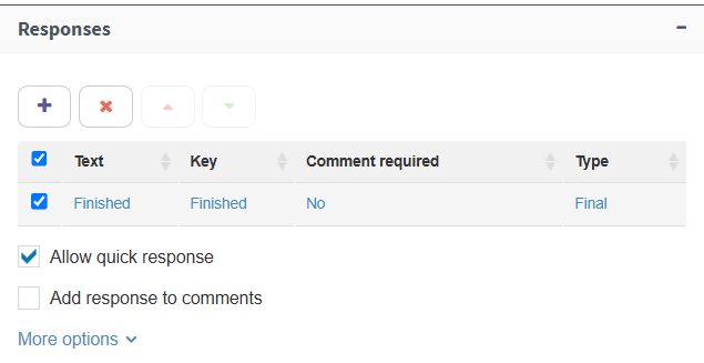
Fig. 444 Added response
Afterwards, the task addressee must be selected. The addressee is the role to which the task will be assigned (through the role, the task is assigned to users: the role members). In this case, the addressee is the “Commercial manager” role. To select it, in “Addressees”, write “Commercial manager”. As you type it, a list will appear in which that role will be available to select. Select it. During the process execution, Qflow will send the task to the user account that was specified as a member of that role (Fig. 445).
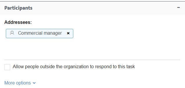
Fig. 445 Entered task addressee
Finally, the data and roles visibility must be specified. In this case, the visibility must be modified so that the “Complaint handler” role is modifiable and required. Additionally, the user who performs this task should see the complaint data, so in the data visibility it must be specified that the application data is visible but not modifiable (“Read only” visibility). Select then, in the roles section within visibility, the “Complaint handler” role, and click the “Required” button ( ).
).
Fig. 446 Roles visibility
In the data section, select all and click the “Read only” button ( ).
).
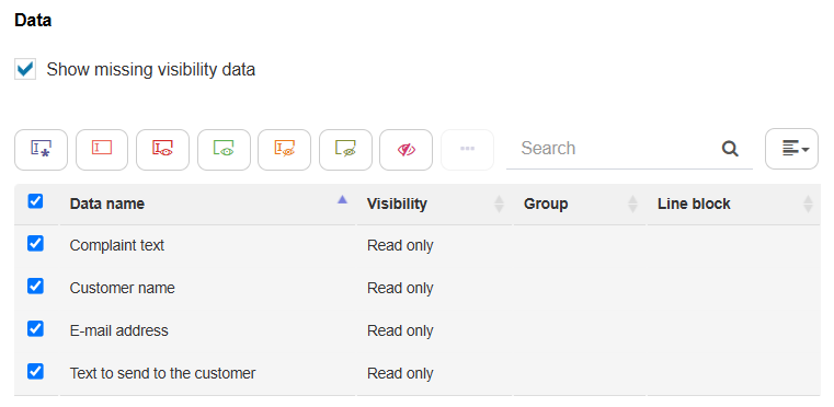
Fig. 447 Read only data visibility
“Handle the complaint” task
Type “Handle the complaint” as the step name.
In the subject type “Handle the complaint and write the text to send to the customer” and then use the application datum “Customer name” as a tag, just as you did with the other user task.
The addressee is the “Complaint handler” role, which for the moment does not have any members, but when the process is being executed, it will have the user that the commercial manager selected in the previous task as a member.
Afterwards, add a response as final so the user can respond to the form. For example, with “Resolved” as its key and text.
The message configuration should look like Fig. 448 shows.
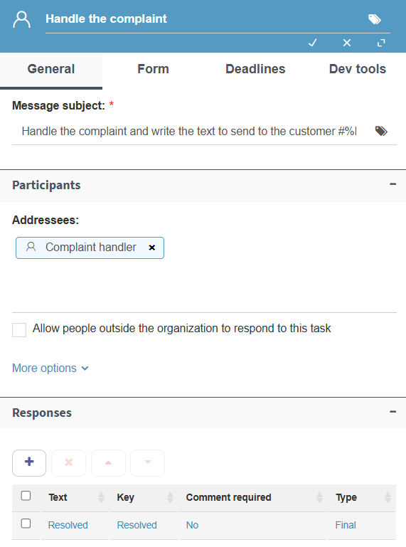
Fig. 448 Message form in the “Handle the complaint” task
In this task, no role should be visible or modifiable, but all the data should be visible and particularly the “Text to send to the customer” datum should be modifiable. Therefore, this datum must have the “Editable” visibility and the others, “Read only” (Fig. 449).
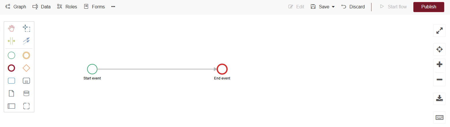
Fig. 449 Data visibility in the “Handle the complaint” task
Mail task
Where the mail task name goes, type “Notify the customer”.
You also have to specify that the addressee is taken from the application datum “E-mail address”. To do this, in the “Addressees” field, type “E-mail address”. A list of application data will appear, from which you must select the corresponding datum. Then, you have to write a subject for the message: type “Complaint resolution” (Fig. 450).

Fig. 450 Mail task configuration until now
Finally, you have to specify that the message body must be what was entered in the “Text to send to the customer” datum by the complaint handler. This is done using a tag, but in this case, to open the list of items that can be used as tags, you must click the text area and press Control + Space (Fig. 451). This is how properties that use a text area work (for example, the code in a script task).
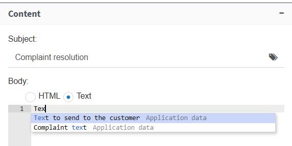
Fig. 451 If you select a text area, when you press Control+Space a list of items that can be added as a tag will appear
When you select the tag, it will appear as in Fig. 452.
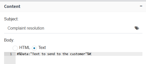
Fig. 452 Tag entered in mail body
Save and publish the template
Once you finish defining the process, save your design. Click on the save icon in the action bar and select “Save and stop editing.
Finally, you must publish the current version of the template. Otherwise, when you enter Qflow Task to start a process, you will not find the template you just designed. To do this, use the publish button that is on the right side of the action bar. You can also look for the template in the package tree, right-click on it and select “Publish” from the menu.
Once the template has been published, to start a process and be able to perform tests, click on the “Start process” button in the action bar. You can also access it directly from Qflow Task. For more information, see the Qflow Task manual.
Second version of complaints process
The previous process has the defect that the commercial manager always has to intervene to select the complaint handler. If this decision could be automatized, at least for some cases, the process could be improved.
A possibility is to categorize the complaints and define a handler for each category. When a process is started, the starter sees a list of complaint categories and selects one. Once the process has been started, the task of handling the complaint is assigned to the handler corresponding to the selected category. An “Other” category can be included to consider complaints that do not adjust to any of the defined categories. Complaints in that category behave as before: the commercial manager decides who will handle them.
To make this change, a new datum is necessary for the category. A datum is associated to a domain, which indicates, among other things, how it is shown and what type of data it contains. A domain can also define a set of possible values for the datum (to learn more about domains, see the Domains section). For this reason, we will create a new domain that will indicate that your data, rather than appear as a text box when it is editable, must appear as a drop down list (“Combo box”). The domain will also define the categories that will appear in the list. In the example, the categories will be three: “Defective product”, “Poor attention” and “Other”. In Qflow Task, it will appear as Fig. 453 shows.
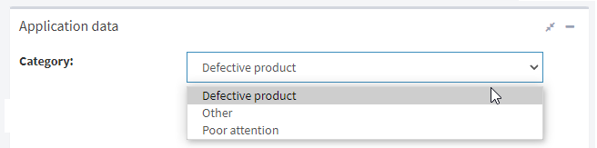
Fig. 453 Combo box in Qflow Task
For each category there will be a user task directed to the handler of that category. To decide which of them the process will go to, an exclusive gateway will be used, which is connected with several elements and associates a condition to each of them. When the process reaches an exclusive gateway, it evaluates the conditions and continues its path by going to the element that is associated to the fulfilled condition. In this case, the exclusive gateway will be connected to each of the user tasks corresponding to each category. Therefore, if the category is “Defective product” or “Poor attention”, the process will continue its path through the task with its respective name. If it is “Other”, it will go to the same task as in the previous version (“Select the complaint handler”).
The new version’s design will look like in Fig. 454. To continue, a description of how to design the new version is provided.
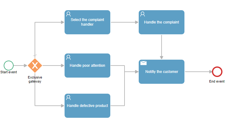
Fig. 454 Second process version
New version creation
Right-click it and, in the context menu, click “Add version” (Fig. 455).
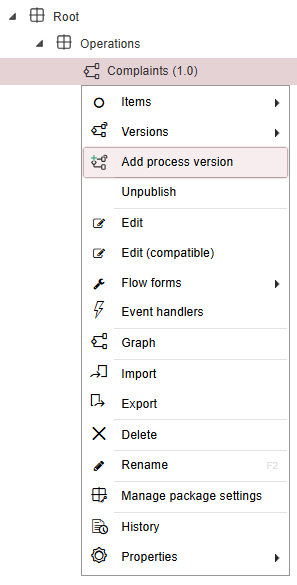
Fig. 455 Add template version
Select, in “Template version pattern”, the “1.0” version (this will create a new version as a copy of the selected one) and enter “2.0” as the version name (Fig. 456).
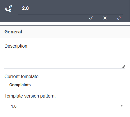
Fig. 456 Add version 2.0
Creating the new domain
To create the list type domain “Complaint category”:
In the action bar, click on the three dots and select “Data domains”.
Click the Add button. In the properties form, aside from entering “Complaint category” in the name, select the “Combo box” control type (a drop down list) and in “Data source”, select “List”. Click the icon
 so Qflow shows the list properties.
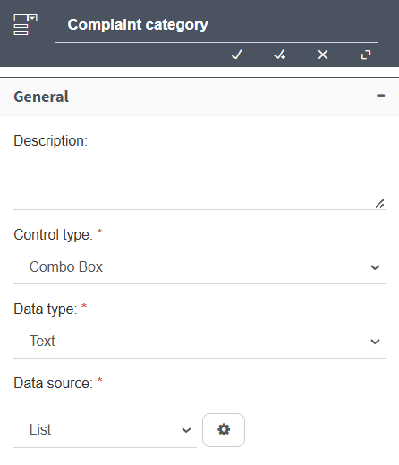
Fig. 457 “Complaint category” domain
Click the Add button. This will add a row. Click “Item 1” in the “Text” column and type “Defective product”. This value will be automatically copied in the “Key” column.
Repeat the procedure to add two more rows: “Poor attention” and “Other”. After that, save the changes.
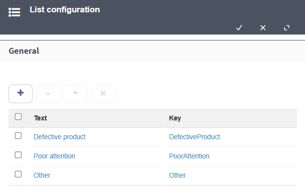
Fig. 458 List elements definition
Save the changes in the list using the “Save” button.
Save the changes in the domain using the “Save” button.
New datum creation
Create an application datum, name it “Category” and where it says “Data domain” select “Complaint category”.
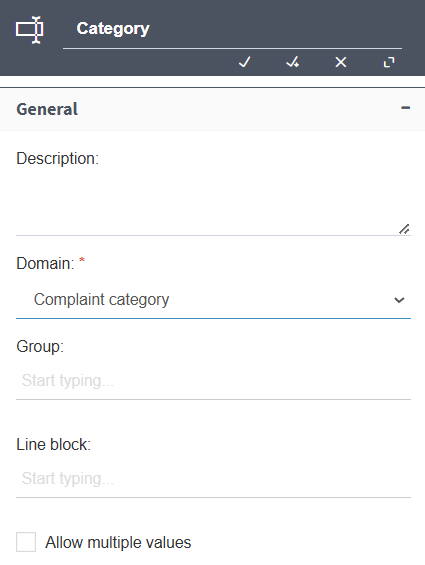
Fig. 459 “Category” datum
Process design modification
To modify the design:
Add an exclusive gateway. To do that, it is necessary to create space between the Start event and the user task. Use the create/delete space tool like Fig. 460 shows.
Fig. 460 Add step between two steps
Add two tasks.
Connect the exclusive gateway with the two new tasks.
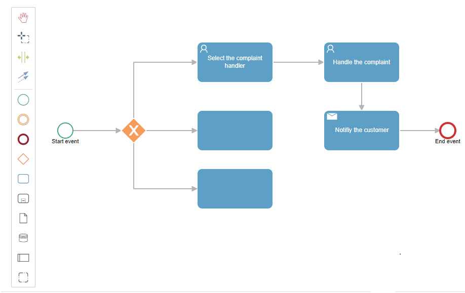
Fig. 461 Add two tasks after the exclusive gateway
Connect the two new tasks with the “Notify the customer” task.
Rename the new elements so they will look like the ones in Fig. 462.
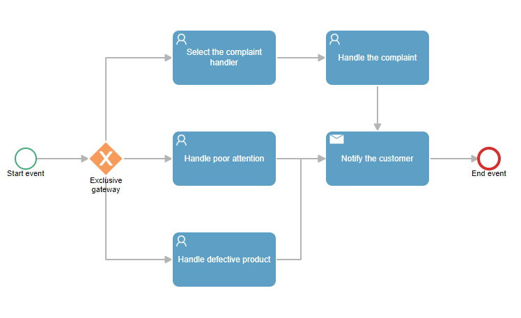
Fig. 462 Finished Complaints 2.0 process design
Modify the start event’s visibility so the “Category” datum has the “Required” visibility. Remember to check the “Show data with absent visibility” box to be able to see it, because by default Qflow only shows the data with editable visibility.
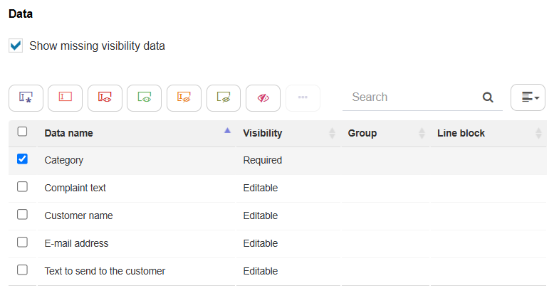
Fig. 463 Edited visibility to include the “Category” datum
Creating two new roles
Create two new roles: “Products handler” and “Attention handler”. Assign your user account as a member (this is only for testing: naturally, in a real case, each one would have a different member).
The roles list should look like in Fig. 464.
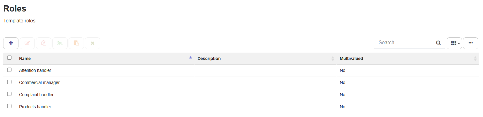
Fig. 464 Complaints 2.0 process roles list
New steps configuration
Configure the “Handle poor attention” task so the addressee is the “Attention handler” role. Do the same with the “Handle defective product” task so the addressee is the “Products handler” role (Fig. 465).
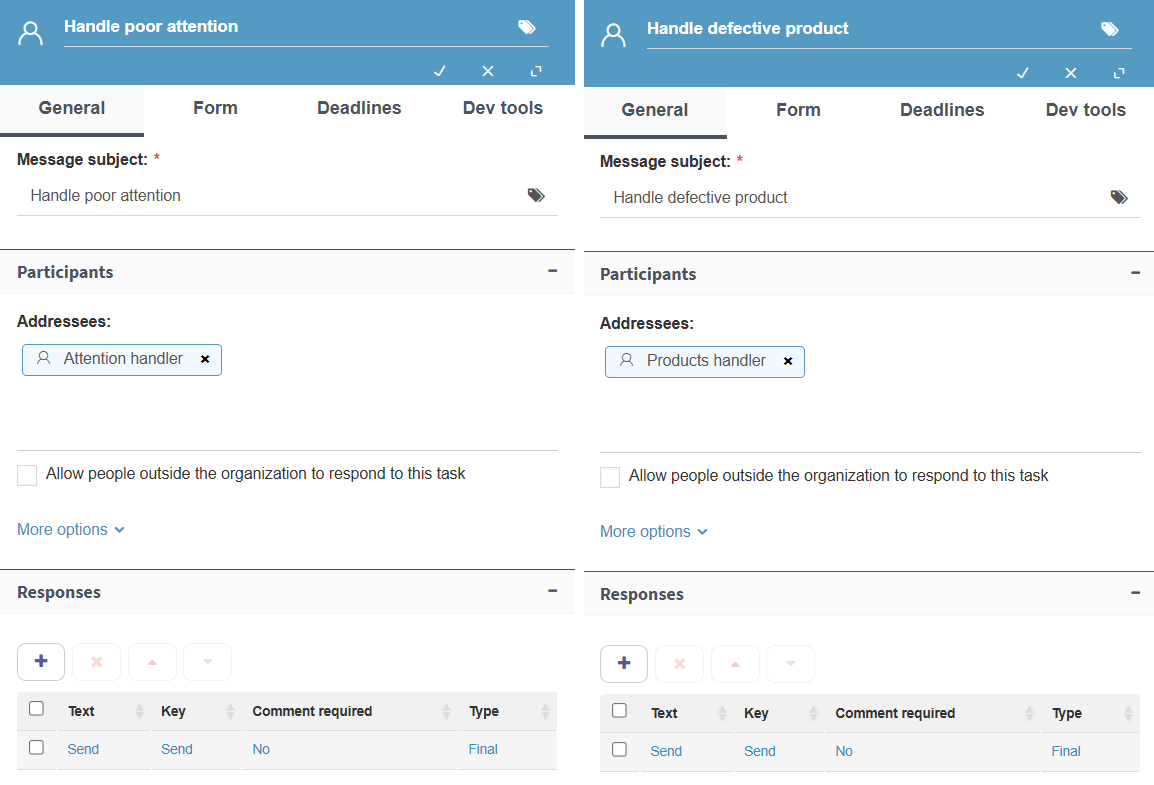
Fig. 465 “Handle poor attention” and “Handle defective product”
Open the exclusive gateway’s properties form.
The gateway’s configuration will be divided into three subsections, one for each of the tasks it is connected to (Fig. 466).
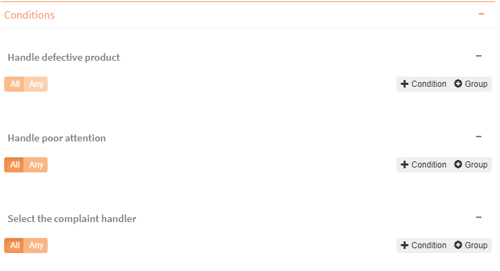
Fig. 466 Exclusive gateway configuration
In the subsection corresponding to the “Handle Defective Product” task, click “+Condition”. This adds an empty condition (Fig. 467).
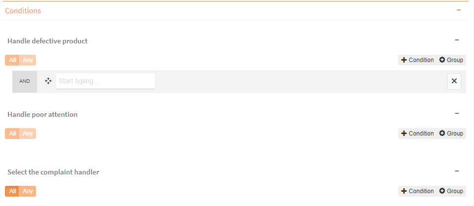
Fig. 467 Add condition
Where it says “Start typing”, write “Category”. When a list with the “Category” application datum appears, select it (Fig. 468).
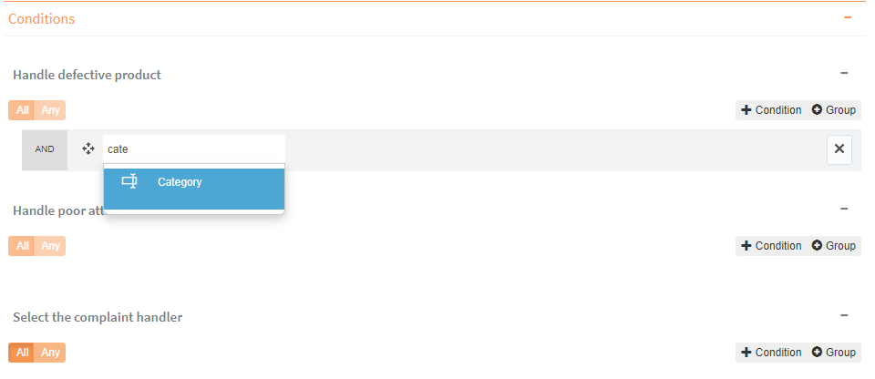
Fig. 468 Configuring condition (1)
In the text box that appears on the right side of the condition, next to the “equals” operator, type “Defective product” (Fig. 469).
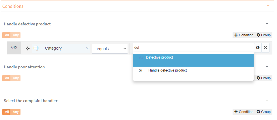
Fig. 469 Configuring condition (2)
Do the same in the subsection corresponding to “Handle poor attention”, but typing “Poor attention“ instead of “Defective product” in the condition. Fig. 470 shows what the exclusive gateway’s configuration will look like.
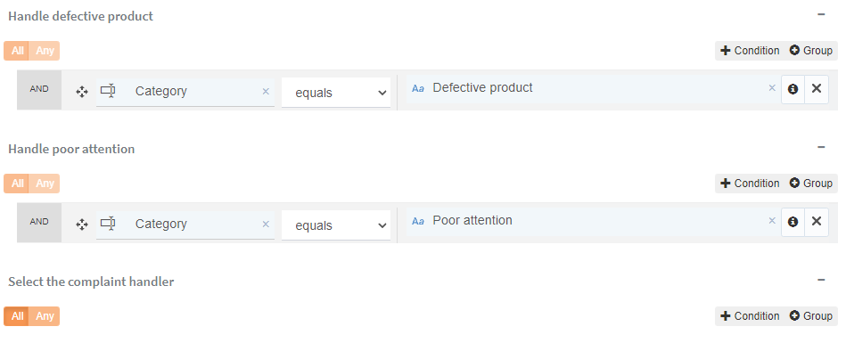
Fig. 470 Exclusive gateway configuration
Click the connection that joins the gateway to the “Select the complaint handler” task. Click the icon
and select “Default connection” (Fig. 471). This way, if none of the other expressions is evaluated as true, this connection will be used.
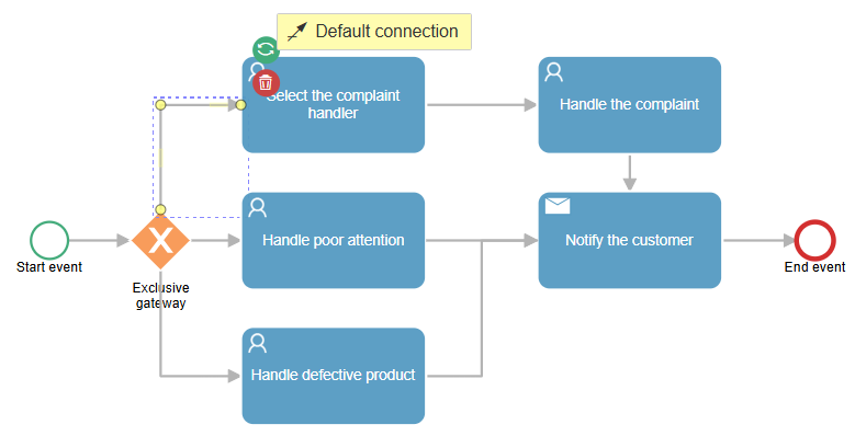
Fig. 471 Assign default connection
Save the changes.
When you are done with the changes, save the process template and publish the new version (see Save and publish the template).
Other possible improvements
In this section, other improvements that could be made to the process are described and it is explained, without going into detail, how they would be implemented, with the objective of showing how other Qflow features that have not been mentioned are used.
Using a web service and your own database
There are different situations in where a user would want to use or update information originated from databases external to Qflow’s internal storage.
In general, a web service (SOAP or REST) is used to access the database and provide Qflow with the functions that allow the user to obtain and save data in it, as well as implement operations related to the businesss logic. For Qflow to be able to access that web service, an Integration (see Integrations) is used. An integration is defined in a similar manner to how application data, domains and roles are defined. You must also specify how to connect to a component (in this case, a web service) and which operation to use (a web service method). It also defines how to exchange data between Qflow and the web service (application data is associated to the parameters of the operation that is invoked and to the result that said operation returns).
Data for the connection to the web service (or to other components, in the case of integrations with components of other types) is usually stored in application parameters, which are also defined in a similar manner to application data, roles and domains (see Application parameters).
Process data manipulation in own code
Another common practice is to develop code that obtains and modifies process data. This allows you to handle some aspects of the process in a more flexible way, so as to facilitate future changes. For instance, in the second version of this process, a user task is used for each complaint category. But this would not be practical if there were a lot of complaint categories. It would also be impractical if the categories were expected to change, since every time a category was added, the process design would have to be modified, probably creating a new version.
It is more practical to use a single user task and a single role, instead of a user task and a role per category. To do that, the “Complaint handler” role can be used, since it does not have a predefined member and can be assigned during the process execution, as was done in the first version. The difference is that it must be done automatically and not manually as in that version. For that, a script task may be used.
In a script task, code that accesses the process data can be written. It is possible to write code that reads the value of an application datum and assigns a member to a role. In this case, you would write code that reads the value of the “Category” datum and, according to its value, the complaint handler would be selected, assigning them as a member of the “Complaint handler” role.
This code may be written in the script task’s properties (see Script task), but it can also be written in an ad-hoc integration (see Integrations).
The functions that Qflow provides to interact with your process data are described in detail in the Scripting interface manual.
Work queues
Another common practice is to use work queues as role members instead of user accounts. Instead of assigning the tasks to particular users, they are assigned to work queues (“Shipping department”). A work queue is associated to permissions that indicate who can take tasks assigned to it. For example, only the users from the shipping department can take tasks from the “Shipping department” queue. That way, when a task is assigned to that work queue, everyone who can take tasks from that queue is notified and any of them can take the task for themselves and take care of it. The concept of a work queue is explained in the Team manual. That manual also explains how to create work queues.
User interface operation
This section explains how to use Qflow Design.
General user interface description
Fig. 472 shows Qflow Design’s interface.
The main interface elements are:
Upper menu: it has options to go to the home, close the session and access the settings screen
Side menu: it allows you to navigate between the package tree, the search panel and the creative space.
Edit zone: it shows the elements that are being worked on and it is where the template diagrams are designed.
Action bar: it allows you to quickly access the template design, its data, roles and process data domains, among other configurations.
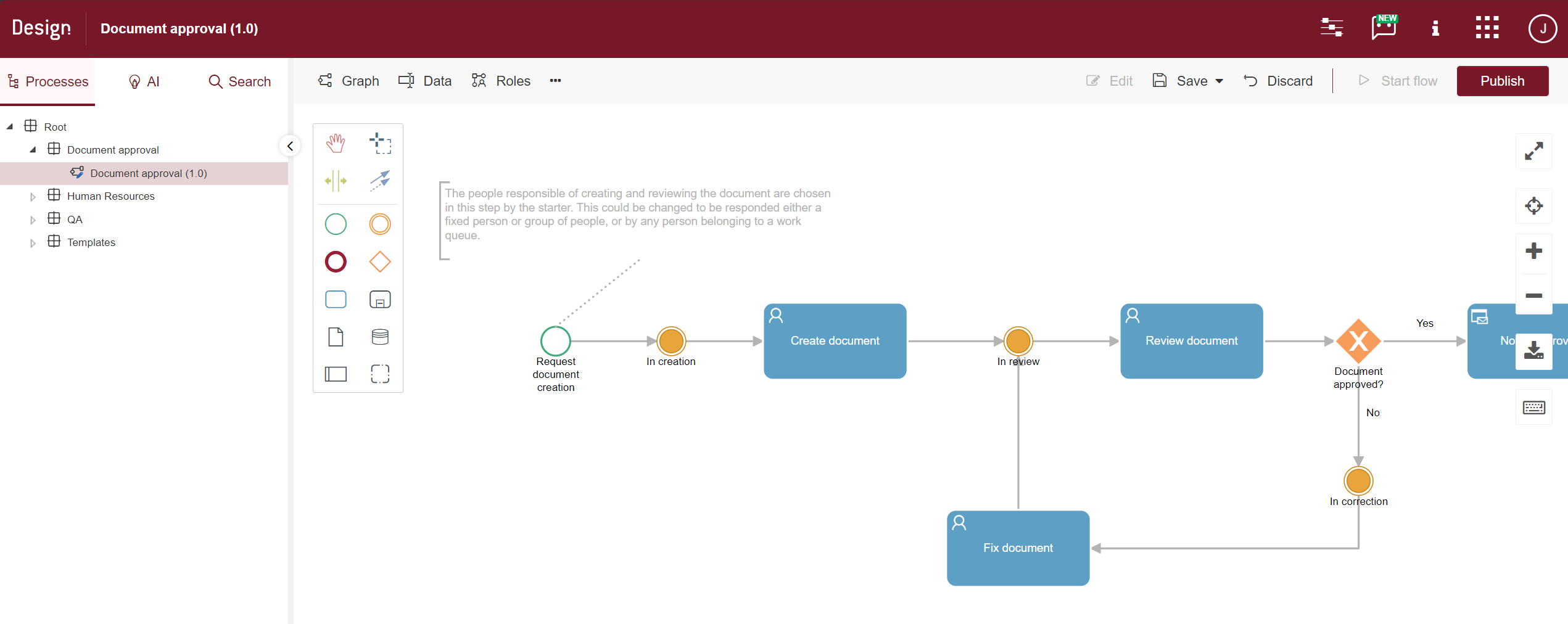
Fig. 472 Qflow Design’s main screen
Upper menu
Fig. 473 shows the upper menu. Next, each of the functions available through it are explained.

Fig. 473 Upper menu
If you click on “Information”, you will see links to the product news, to Qflow’s support and community forums and to this manual, as well as the version of the product you are using.

Fig. 474 Product information
The tool access menu allows you to easily navigate between the tools to which you have access permissions. When clicking on any element in this menu, your browser will open a new tab with the selected tool, where we will be logged in with our user to start working.

Fig. 475 Tool access menu
The help chat button allows you to show or hide the artificial intelligence-powered assistance chat.

When you open the “Current user” option, the system displays the user’s preferred time zone and the sign out button. This time zone is used in all of Qflow’s dates and times for the current user. The preference is shared by all the product tools, so its modification in one of them affects the others.

To edit the time zone, you must select the “Current user” option from the menu. This will open a right panel with the list of available time zones. After the time zone has been selected, when you save the panel, the page will be automatically refreshed so that the change takes effect. If you have more open windows with some of Qflow’s tools, these have to be refreshed manually so that the change takes effect.

The settings function has the option for the tool’s permissions management, which is explained in the Qflow Team manual.
Sidebar
The side menu facilitates navigation between the package tree, the creative space and the search panel. In the package tree, you can view and manage the elements of the hierarchical package and template structure. In the creative space, you can access the templates generated with Artificial Intelligence. Finally, the search panel allows you to search for data, roles and other process elements, as well as packages and templates within this hierarchical structure.
Search
To open the element search panel, you can access it by going to the “Search” tab in the side menu, or by pressing “Ctrl + Shift + F”.
Quick search
A quick search consists of typing part of the name of the element you are searching for in the text box. The elements that can be found in this mode are those belonging to the tree, that is, the whole solution’s packages, templates and versions, as well as the roles, domains and data located in the package that is selected in the tree or one of its parents. Qflow filters the elements that are shown in the edit zone, hiding those that do not contain the entered text (Fig. 476).

Fig. 476 Quick search
Advanced search
The advanced search (Fig. 477) is accessed by clicking on the “Advanced search” checkbox. It allows you to easily find items that are used in the processes’ specifications (for example, application data). This is especially useful when you remember part of an element’s name, but not in which package, process template or version it is located. The search screen allows you to enter the following data:
Name: name of the element that is being searched for.
Type: you will be able to filter which types of elements you wish to search for (packages, steps, application data, process template roles, data domains, custom forms, integrations, event handlers, worklets, validations, bots and/or application parameters). Additionally, it is possible to select two or more types, allowing you to obtain the different required data in a single search.
Look in: it allows you to specify in which packages, process templates or versions to search (the options mention “packages”, but process templates and versions are also considered packages for this purpose). Restricting the packages in which to search reduces the search time. Options are:
Current package and parents: it searches the current package and the ones above it in the hierarchy. It does not search the packages contained in the current one.
Current package: it searches the current package.
Entire solution: it searches in the entire hierarchy among the elements that already existed the last time it was checked in, not the new ones that were added in the case it is checked out.
Difference in versions
Custom forms and worklets are not available in the advanced search in the Cloud version.
Once you click the search button, the results will appear in descending order by item name in the lower part of the screen and you will be able to access the listing or process design to which the element belongs by clicking “Go to item” (→). In the case that you want to access a package or process template, a button will be enabled that will allow you to see the element in the tree (Fig. 476).

Fig. 477 Advanced search
Packages tree
The packages tree is similar to a hard drive’s folder structure, which may contain subpackages (child packages), which may in turn contain subpackages, in the same way that a file system has a root folder with subfolders, which in turn may contain subfolders.
Additionally, a package can contain process templates. All these elements are shown in the packages tree and can contain process items (for example, application data), which are not shown in the tree. However, the options to view, create and modify them are accessible from the packages tree.
A package can be shown open (its children are shown) or closed (they are not shown) (Fig. 478). To open a package, click on the triangle that is to its left, which indicates if it is open or closed.
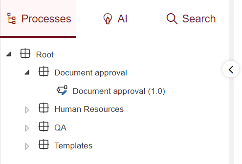
Fig. 478 Packages tree.
When you double-click on a package, its properties form opens in a panel (the properties of the tree elements are described in Working with packages, process templates and versions). On the other hand, if you double-click on a template, the graph of the version you are working on opens.
For each element, there are several operations available which are accessed through a context menu that appears when you right-click it. The options that can appear in the context menu are the following:
Items: when you click this option, a submenu to select the type of items that you wish to see or modify appears. When the item type is selected, Qflow opens a screen that shows the items of the selected type belonging to the package. In that screen, the existing items can be seen and modified, aside from creating new ones. Items lists are described in general in Items lists. Each item type and its properties are described in detail in Process items.
Change control options: change control options prevent an element from being modified by more than one user simultaneously. This prevents modifications losses that would occur if this control was not done.
Edit: it unlocks the element for the user who selected it, allowing them to modify it, and prevents others from doing so.
Edit (compatible): unlocks a process template for the user who selects it, but does not allow them to make some changes that could affect running processes (for example, it does not allow them to delete steps).
Discard: discards all the modifications made in the template since the last time the changes were saved.
Save: saves the changes made in the template. If the template was already published, the changes will impact the processes that are started from it. You can choose between saving and continuing editing or saving and finishing changes. This last option not only persists the changes made, but also releases the template so that another person can work on it.
Publish: publishes the template that is being edited, saving the last changes. After it is published, the process will be available to be started in Qflow Task. Each template can only have one published version, so if there is already one, it will be replaced.
Unpublish: it is only available if we are working with the published version of the template. Keep in mind that if you unpublish a template, processes cannot be started with it.
Add sub package: only available for packages, it allows you to add a package inside the selected package. When this option is selected, Qflow shows a form in the edit zone to enter the name and description of the new package.
Add process template: it allows you to add a process template inside the selected package (this option is only available for packages).
Delete: it allows you to delete the selected element. In the case of packages, it only appears if it does not have subpackages. For templates, it deletes the template along with all its versions.
Delete version: it allows you to delete one of the versions of the selected template. It only appears if the template has more than one version.
Refresh: it updates the selected element and its descendants on the screen to reflect the last changes occurred. For instance, if a user recently added a package and another user does not see it because it is too new, when they refresh the container package, the tree will reflect the change and show the new package.
Stages: it shows a screen with the defined stages for the selected template and it allows you to modify them. (For more details, check the Stages section.)
Add process version: it adds a new version to a template.
Graph: it opens the process design (diagram) of a version.
History: it shows the history of actions performed on the element (who did what and when). The time zone in which the dates are shown is also indicated.
Properties: it shows the element’s properties form. In the case of templates, a submenu is displayed that allows you to access the properties of the template or the version you are working on.
Process forms: it opens a submenu with two options: “Flow edit form” and “Flow form”. These options allow you to open those forms’ properties windows to:
Define the visibility of data, roles, attachments and comments (see Data, roles, attachments and comments visibility).
Associating validations with forms (see Validations).
Associating event handlers with processes (see Event handlers).
Export: it exports the element to an XML file, so that it can be imported somewhere else Qflow is installed. There is more information in the Exporting packages, templates and versions section.
Import: it imports an XML file that contains packages or templates definitions. There is more information in the Importing packages, templates and versions section.
Creative space
Qflow Design’s creative space shows a list of process designs that were generated using our artificial intelligence assistant, but have not yet been confirmed as processes that are included in our packages tree. These processes are stored for each user on the browser’s memory.
For more information, see the Artificial intelligence assistant section.
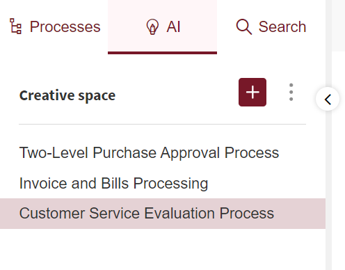
Fig. 479 Creative space
Exporting packages, templates and versions
To export a package or template, do the following:
Save and finish the changes of the package or template.
Right-click the package or template in the packages tree. Qflow will show a context menu.
In the context menu, select the “Export” option. Qflow will show you a window like the one in Fig. 480.
In the case of templates, it is possible to choose between exporting the template only with the version you are working on or including all the available versions. For packages, you can choose to export only the current package or export the complete package along with its subpackages and templates. In both cases, the option to compress the files before exporting is offered.
Click “Export”.
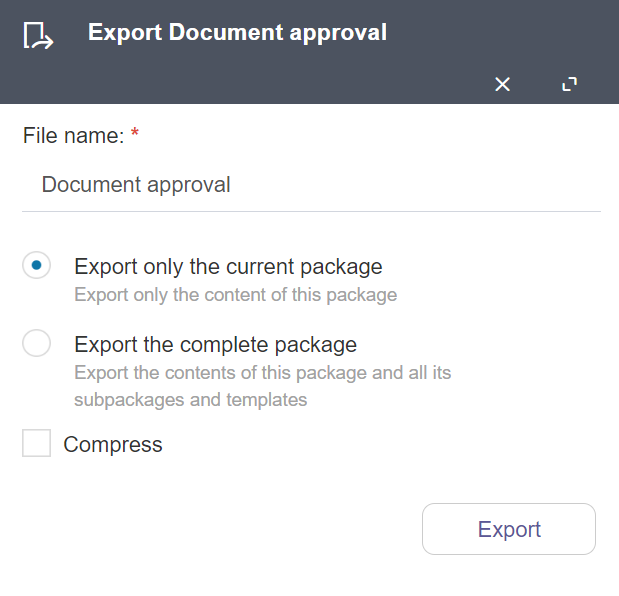
Fig. 480 Export package panel
Importing packages, templates and versions
To import a file created by a previous export, do the following:
Select the package or template where you wish to import the file’s content and right-click it.
In the context menu, select “Import”. Qflow will show a window like the one in Fig. 481.
Select the file format to import. The supported formats are Qflow’s native format and BPMN XML.
Select the file to import and mark the options you desire:
Update existing application parameters: if this option is checked, the application parameters’ values will be substituted by the values of the imported application parameters. Otherwise, this will not happen. This is useful because the same parameters can have different values in different environments.
Fix missing references: this option indicates to Qflow that it should correct references to elements that do not exist in the database in which the import is being done. For instance, if a user that a role references is not found, Qflow will ignore that user in the import. If this option is not checked, when Qflow finds a missing reference, it will interrupt the import and leave the database in the same state as it was previously.
Click “Import”. If the package, template or version contained in the file already exists, Qflow will allow you to choose between updating the existing package, template or version with the imported data, or creatinga new one. This allows you to update processes that had been imported from development environments.
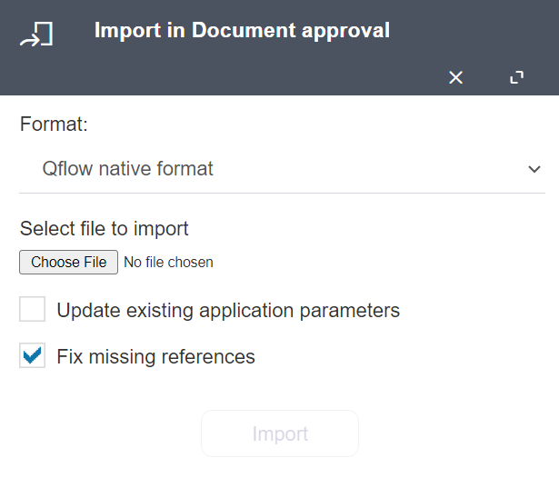
Fig. 481 Import panel
Home page
When a user logs in to Qflow Design, o when they click on the Home icon in the upper menu, Qflow shows the home page, similarly to what is shown in Fig. 482.
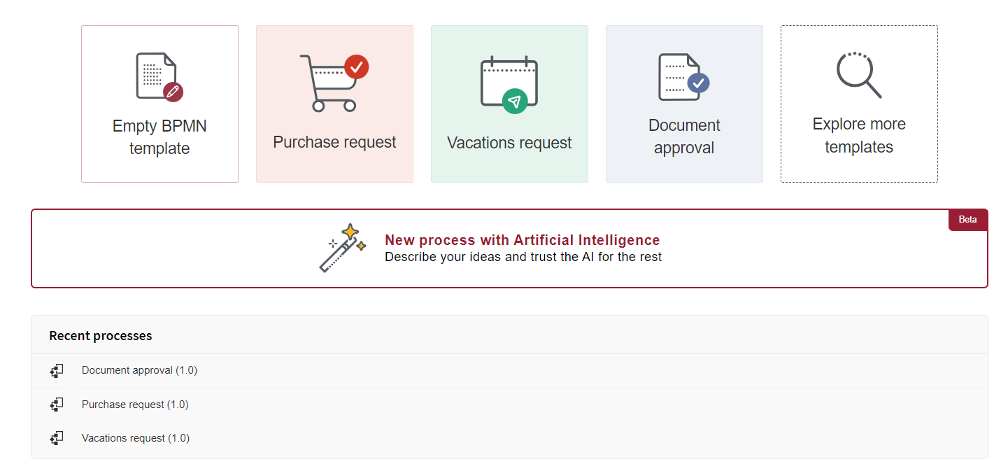
Fig. 482 Home page
In the upper section you can find options to create templates. You can start with an empty template, or select any of the pre-created templates offered by Qflow. Click on “Explore more templates” to see the full catalogue of pre-created templates (Fig. 483).
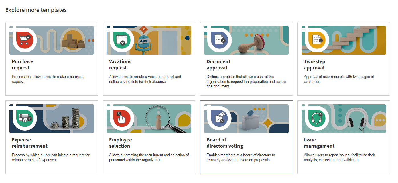
Fig. 483 Explore more templates section
The “New process with artificial intelligence” option will take you to the process generation with AI form (Fig. 514). In this view you can type a description for our assistant to generate a process based on it.
The “Recent processes” section shows a list of the templates with which you have recently interacted. Click on the list’s elements to open the design of the corresponding template.
Working with packages, process templates and versions
This section explains how to create and modify packages, process templates and versions, but not how to design a version’s diagram. For the latter, check the Designing a version’s process section.
Creating a package
To create a package:
In the packages tree, right-click the package inside which you wish to create a template. This shows the context menu for the selected package.
Select the “Add sub package” option. This shows a form like in Fig. 484, in which it is indicated in which package the new package will be added and in which there are two text boxes to enter the package’s name and description.
Enter the new package’s name and description and click the Save button.
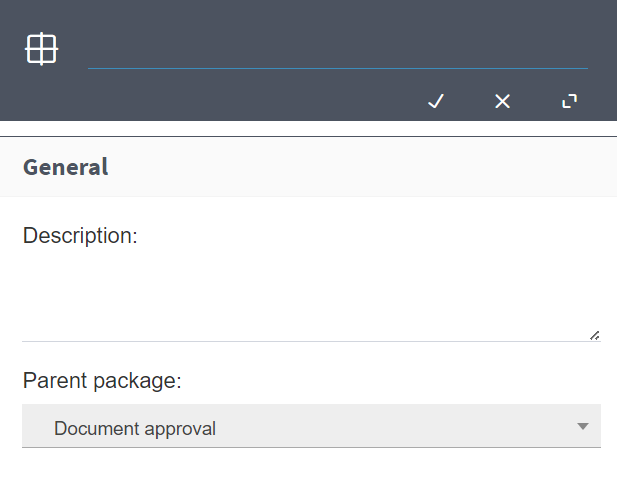
Fig. 484 Create package
Creating a process template
To create a process template, do the following:
In the packages tree, right-click the package inside which you wish to create a template. This shows the context menu for the selected package.
Select the “Add template” option. This shows a form like the one in Fig. 485, in which it is indicated in which package the new template will be added and in which there are two text boxes to enter the template’s name and description. You must also select the template pattern (in Fig. 485 the option that appears selected by default is “Empty BPMN template”, but you can start from a set of pre-created templates by Qflow. For more information about these templates, see Pre-created templates).
Enter the name and description of the new template, check the option “Create process container subpackage” if you want the new template to be created inside a subpackage with the same name. Then, click the OK button.
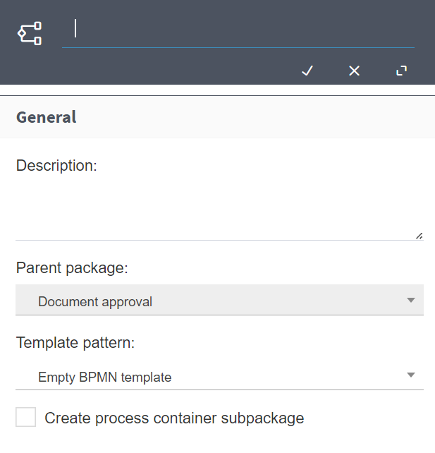
Fig. 485 Create new template
Creating a version
To create a version, do the following:
In the packages tree, right-click the process template in which you wish to create the version. This shows the context menu for the selected template.
Select the “Add process version” option. This shows a form like the one in Fig. 486, in which it is indicated in which template the new version will be added and in which there are two text boxes to enter the version’s name and description. If the selected template already has versions, in the “Template version pattern” field you can select one of them for Qflow to copy. For example, in Fig. 487 you can select versions 1.0, 1.1 or 1.2. If the selected version has a name that follows Qflow’s standard (“1.0”, “1.1”, etc.), Qflow will automatically enter the name that, according to that standard, would correspond to the next version’s name (if the selected version is “1.1”, Qflow will put “1.2” in the name text box). You can also create a version without copying any other (“Template version pattern”). In this case, the new version will be created with a start event and an end event.
Enter the new version’s name (if it is necessary) and description and click the Save button.
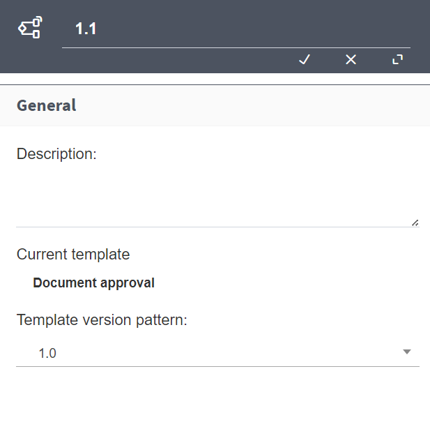
Fig. 486 Create a version
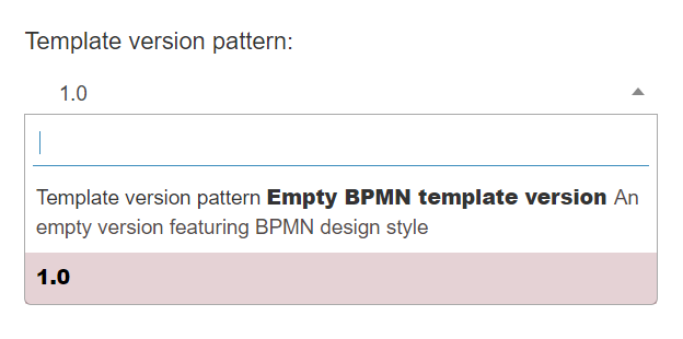
Fig. 487 Select a version pattern
Modifying the properties of a package, process template or version
Packages, process templates and versions have additional properties to those shown when they are created (name and description). To modify the properties of a package, find it in the packages tree, right-click it and select the “Properties” option. In the case of templates, when you right-click and select “Properties”, two options will be displayed: one to access the template’s properties and another for the properties of the version in which you are currently working. This makes Qflow show the selected element’s edit form (Fig. 488).
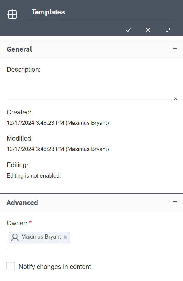
Fig. 488 Package properties
This edit form has two groups:
General: it shows and allows you to modify the name and description, aside from the following data (all dates and times are shown in the user’s preferred time zone):
Date and time in which the element was created and who created it.
Date and time of the last modification made to the element and who made it.
Whether the element is being edited or not. If it is being edited, it is indicated when it was taken and by whom.
If the element is a process template, the published version is shown and you are allowed to change it.
If the element is a version, it is shown if it is a draft or not. A draft is a version that is not valid to be published (it would produce errors when executed), but which can be saved. Once a version is published, it is not possible for it to be a draft again.
Advanced: the advanced subform’s properties are:
Common to packages, process templates and versions:
Owner: it indicates which user is the element’s owner. The element’s owner is a system user. The owner can be removed by clicking the cross that appears in the rectangle containing their name, so the element no longer has an owner. To specify an owner, start typing their name and when the username of the person who you wish to assign to the element appears, select it.
Notify changes in content: if this box is checked, each time the element is modified, Qflow sends a notification to its owner.
Templates also have the following advanced property:
Notify flow in error: if this box is checked, each time a flow based on that template has an error, a notification is sent to the owner.
Manage package and process template permissions
To manage the permissions of a package or template, find it in the packages tree, right-click it and select the “Manage package permissions” option (Fig. 489). This makes Qflow show a form like the one in Fig. 490. This form shows a table with all the defined permissions. For each one, it shows for which role the permission is, the role’s description, a list of allowed actions and a list of denied actions. The list can be filtered as explained in Items lists and it can also be modified, adding, removing and modifying elements.
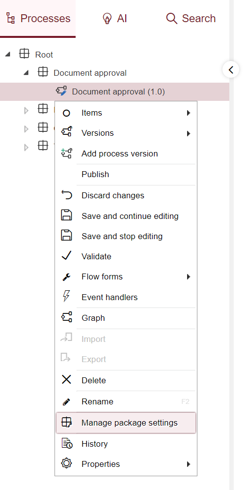
Fig. 489 Manage package settings
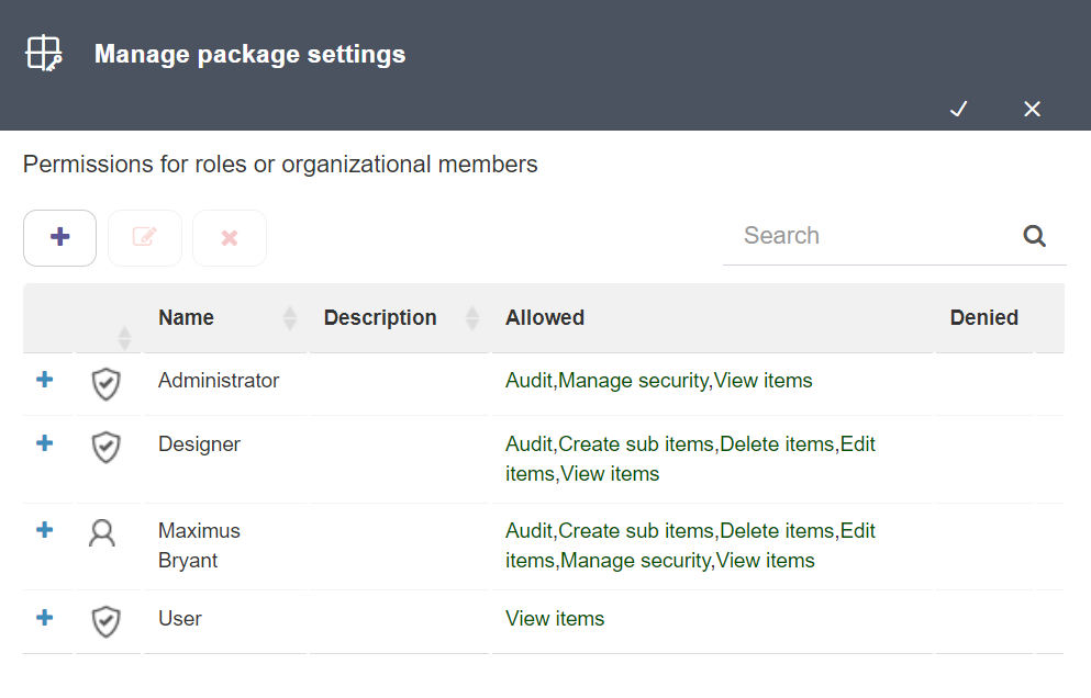
Fig. 490 Manage package settings panel
To add a permission:
Click the Add button. This makes Qflow show a role search bar (Fig. 491).
Select the permission recipient. To do this, type part of their name in the search bar (where it says “Start typing a role”) and when you see it in the list that appears, select it. A permission recipient can be an element of any of these types:
Security role (do not confuse it with a process role; process roles are used to assign tasks in a process and cannot be selected as permissions recipients)
Node
Group
Work queue
User
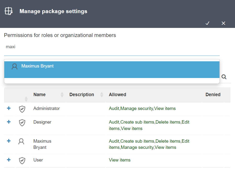
Fig. 491 Selecting a role
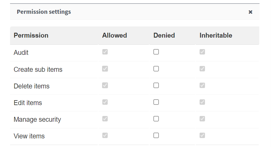
Fig. 492 Permissions
For each of the permissions shown in that window, indicate whether it is allowed or denied, and if it is inheritable. When a user has an inheritable permission on a package, that permission is also applied to its descendants, unless it is explicitly denied in any of them.
The permissions that can be assigned are:
View item: it allows you to view the package and the elements defined in it, such as application data, process roles, etc.
Edit item: it allows you to modify the package and the elements defined in it, such as application data, process roles, etc.
Create sub items: it allows you to create elements inside the element.
Delete item: it allows you to delete the element.
Audit: it allows you to view the element’s audit information.
Manage security: it allows you to add and modify permissions on the element for users, groups or roles.
A user has permission to perform an action if the following requirements are simultaneously met:
The user is associated to some security role, group, node or work queue that has permissions to perform that action or their own user account has that permission directly.
The user is not associated to any security role, group, node or work queue to whom that permission was denied or their own user account has been denied that permission.
It can also happen that the user does not meet these conditions, but is the substitute of one that does. In that case they would also have permission. For more details on permissions management in Qflow, check the Qflow Team manual, where it is also explained how to associate users with security roles, nodes, groups and work queues.
Pre-created templates
In addition to the empty template pattern selected by default, Qflow provides a set of patterns created when the system is installed. These templates represent some business flows and operations that are commonly automated. We can select these templates from the “Template pattern” list in the template creation panel, or by using the buttons on the home page (see Fig. 482).
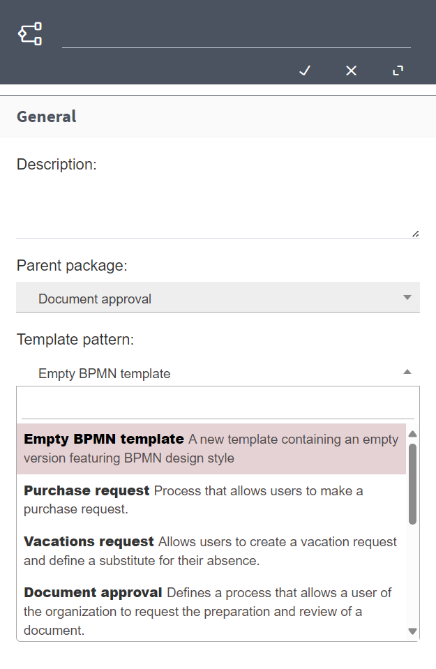
Fig. 493 Pre-created template list
Qflow’s pre-created templates are the following:
Document approval: this process represents the case of a document approval, including the creation, revision, approval and notification to elaborators and to a distribution list, and optionally, a task to upload the file to a document repository.
Vacations request: it defines a process in which an organization member can make an application for their vacation. It includes a stage of supervisor approval, verifying and updating the number of available vacation days, define substitutes and sending reminders previous to the start of the vacation period.
Two-step approval: it defines a more generic process, in which an approval is done by two approving users, started by an application form in which the user that starts the flow must provide the motive and planned date for that wich needs the approval.
Expense reimbursement: it defines a process in which the starting user presents one or more expenses, with their justification, an approval stage in which the expense can be approved or not (in the latter case, it allows for a revision of the application to be re-evaluated), tasks to represent the action of financial personnel moving funds, and notifications to the applicant, for approval or rejection.
Purchase request: it defines a process in which the starting user presents an expense with justification, amount and currency used, followed by an approval stage that can be done in two stages if the amount exceeds a preset amount. Approval tasks have time controls defined to make sure applications have a resolution. It also includes notifications to the applicant for its approval or rejection.
Employee selection: it includes the review of submitted resumes, coordinating and conducting interviews. These interviews can be of various types, such as pre-selection, competency-based, psychotechnical, technical evaluation and verification of work references. Once the interviews are conducted, the process proceeds to preparing and presenting a job offer. At the end of the process, the candidate is notified of the outcome of their application, whether it is accepted or rejected. The process also has has time controls to ensure efficiency in coordinating interviews, and sends weekly reminders to ensure scheduling them.
Board of directors voting: it allows members of boards of directors to participate in voting on proposals remotely. The template includes stages of review, voting, modification and a face-to-face meeting if necessary. At the end of the process, users will be notified if the proposal was rejected or approved.
Incidents support: it allows users to report incidents. The template includes stages of evaluation of the incident, assignment of person in charge of the resolution, resolution of the incident and validation of the resolution. In turn, it is also contemplated stages where more information can be provided if required. At the end of the process the users will be notified whether the incident is resolved or not, or whether it was dismissed.
Note
These templates are created with most of the design configuration already done, but in various cases it will be necessary for them to be adapted to the needs and particularities of each organization. It is recommended to read the notes included in the design of these templates to make the final adjustments to their configuration.
Items lists
A process design also involves defining items that the process uses. For example, to assign tasks to people, roles are needed. To handle data, some of which may be necessary to define the process flow, application data is nedeed. To access external systems’ functions, integrations are necessary and it is recommended to use application parameters that contain information to access those systems. This section explains how to use Qflow Design to create, modify and delete items. It does not explain what each item type is for or what properties it has. To find information on this topic, check the Process items section.
Fig. 494 shows the application data list, which is a typical items list. The items list is shown as a table with several columns, the first of which contains boxes that allow you to select one or more items (if the header box is checked, all items are selected).
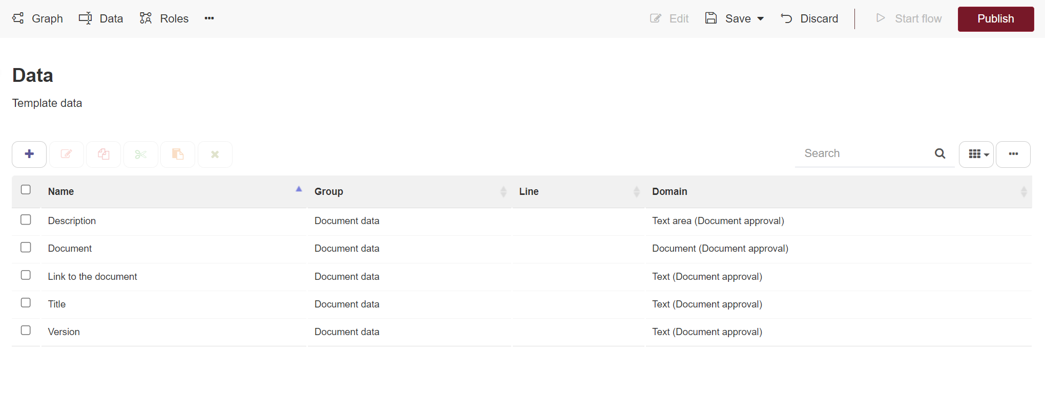
Fig. 494 Application data
In the upper left section are icons corresponding to the following operations:
Add: when you click this icon, Qflow shows the item’s basic properties form. To create an item, fill in its properties and click the accept button. The detailed description of the properties of each item type is found in Process items.
Modify: when you select an item and click this icon, Qflow shows the item’s basic properties form (Fig. 495), which is the same form as the one used to create an item.
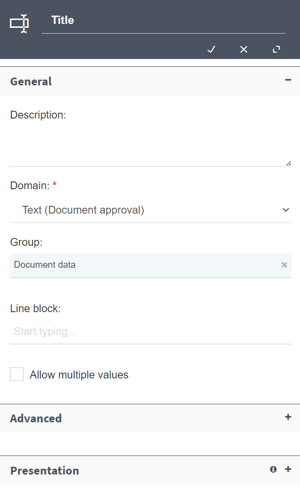
Fig. 495 Application data properties
Cut: it allows you to cut elements to paste them in another package: when they are pasted, those elements are deleted from the original package. IMPORTANT: if an element is cut and pasted in a different branch of the tree than the original, inconsistencies can be created, since other elements from the original branch that used the moved element will no longer have access to it. Additionally, it is a good practice to save the changes in both packages, both the original and the destination.
Copy: it allows you to copy elements to paste them in the same package or another one. When they are pasted in the same package, the new elements will be renamed, adding “_1” or changing “_X1” for “_(X1 + 1)” if the name ended in “_X1”, with “X1” being an integer number.
Paste: it pastes the cut or copied elements.
Delete: when one or more elements are selected and you click this icon, the selected elements are deleted, confirming it previously.
These icons are enabled or disabled according to which elements are selected. For instance, the “Modify” icon is only enabled if there is exactly one selected item, because if there are no selected items, there is no item to which the modification operation can be applied, while if there is more than one, it is impossible to determine to which of them the operation applies. Additionally, if the package is checked in, the only one of these actions that is possible is “Copy”.
Also in the upper section, but towards the right, there is a text box that allows you to filter the elements that are shown in the list. By writing text in that box, the list will hide those elements that do not contain the entered text in any of the columns. To the right of that text box, there is a button that allows you to specify which columns you want to see.
To promote good practices in process design, the template elements are shown by default. However, it is also possible to access the elements of the version you are working on, if you wish. To do this, use the button located to the right (Fig. 496).
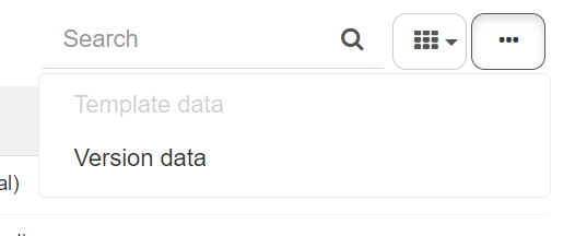
Fig. 496 Switch between template data and version data
Stages
Qflow allows you to define stages for a process template. A stage defines an “Expected time” and a “Maximum time”, which determine two deadlines for the stage’s end. Both for the expected time and the maximum time, a list of process template roles can be specified. These roles will be notified if, once the specified time has passed, the stage has not finished yet. The expected time is an estimate of how long the stage should last in a normal case. The maximum time indicates a more important deadline than the expected time: the process is not supposed to remain in the same stage for longer than it is indicated in the maximum time.
When a process is divided in stages, it has more tracking options in Qflow Task.
Stages are linked to process sections through the start event and intermediate events.
To access the form that allows you to define stages, open the template’s context menu by right-clicking it in the packages tree and selecting the “Stages” option inside the items submenu (Fig. 497).
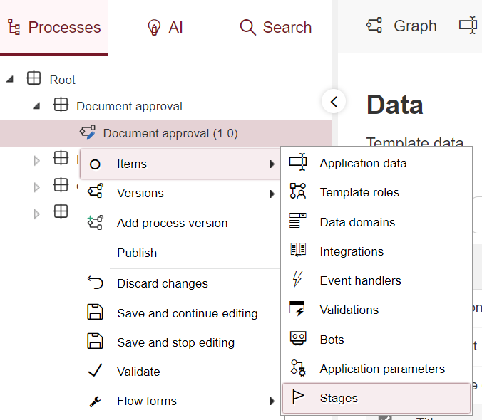
Fig. 497 Access stages listing
The stages definition form behaves in the same way as the items lists. The expected time and the maximum time are defined in the same way as other deadlines (explained in Deadlines configuration).
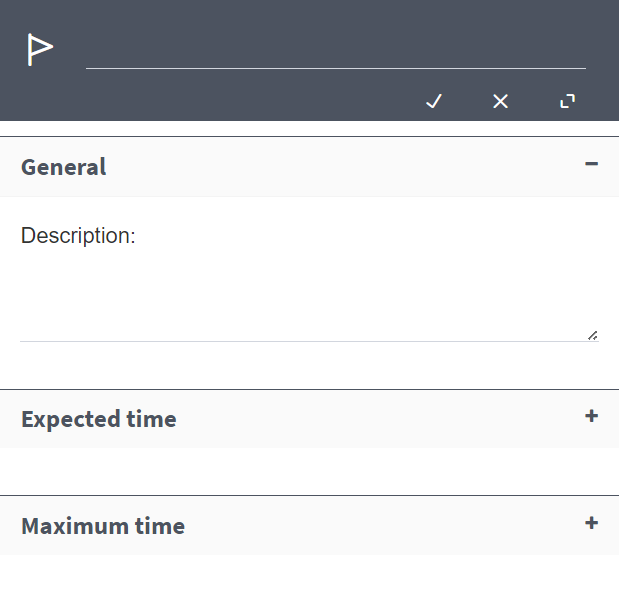
Fig. 498 Stages configuration
The “Use calendar” option allows you to select a calendar to be used when expirations are calculated. If this option is not checked, expirations will be calculated without considering weekends, holidays, etc (Fig. 499). For more information on calendars, check the Qflow Team manual.
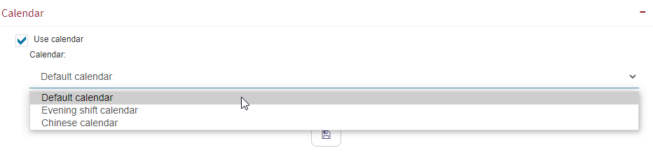
Fig. 499 Configuring “Use calendar”
Designing a process version
To modify the design of a template, double-click it in the packages tree and, in the action bar that appears at the top, select the “Edit” option (Fig. 500).
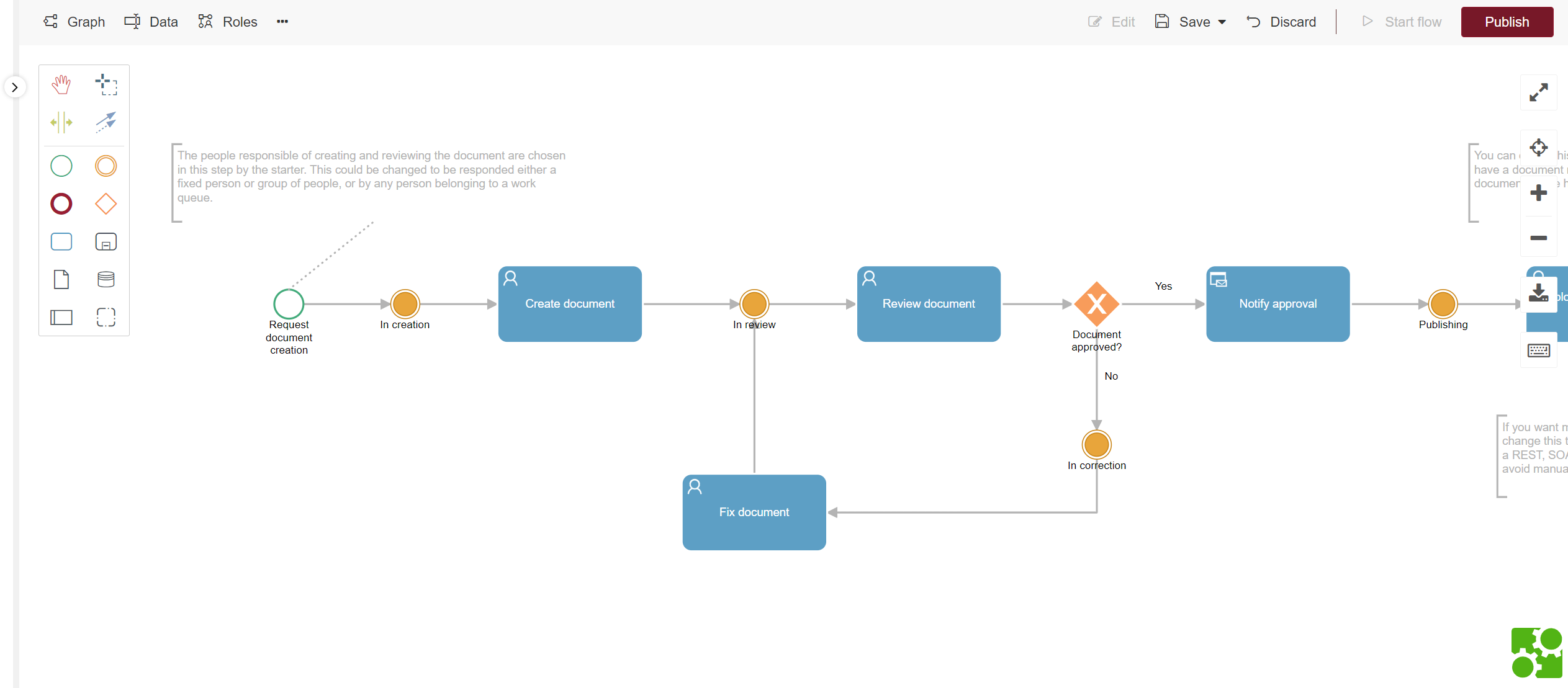
Fig. 500 Designer
In the designer’s left section there is a toolbox, which is divided in two parts. The first one shows design tools, while the second one has elements that can be added to the diagram. In the designer’s right section, there is a series of buttons whose objective is to facilitate the viewing of the diagram, apart from allowing you to save it and export it. All these options are explained next.
Design tools
Fig. 501 shows the design tools.
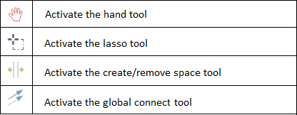
Fig. 501 Design tools
Activate the hand tool: if you select this tool and keep the mouse button clicked on the design surface while you move the mouse, you will move the design surface. For example, if there is no more available free space on the surface and you wish to add something under the elements that are already on it, you can use the tool and, keeping the button clicked, move the mouse upwards. This will move the design surface upwards, as though the surface were a sheet of paper and you pressed it with your hand and pushed it up, so the paper’s upper half was no longer visible and the lower half was visible.
Activate the lasso tool: with this tool you can draw a rectangle on the design surface. The elements that remain inside the rectangle and their connections will be selected.
Activate the create/remove space tool: with this tool you can create space between two parts in the diagram, by keeping the mouse button pressed down and moving the mouse to the right. The effect is as if all the elements that are on the mouse’s right were pushed to that side, generating space between their new positions and the ones they occupied before. In a similar way, you can do the same but moving the mouse to the left, which has the opposite effect: the middle space is removed.
Activate the global connect tool: this tool allows you to connect two elements, although it is not the only way to do this.
Elements that can be added to the diagram
Fig. 502 shows the elements that can be added to the diagram. The ones that are events, gateways and activities are described in more detail in the Process design elements section.
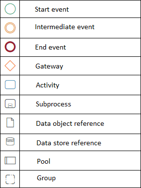
Fig. 502 Tools to add elements to the design
Start event: it marks where the process execution starts.
Intermediate event: it allows you to mark a milestone in the process execution (for example, that a phase of the process is over). It can also be attached to an activity, in which case it is an intermediate boundary event.
End event: it marks where the process execution ends: when a process reaches an end event, it finishes its execution.
Gateway: it allows you to control the process flow. Exclusive gateways allow you to choose a path between several possible ones in a process. Inclusive gateways allow you to create several parallel paths.
Activity: it represents an action or task. It can be a task performed by a person, but it can also be an action automatically executed by some system component.
Subprocess: it groups several elements.
Data object reference: it is a decorative element that represents data that is used in some activity. It is connected to another element, typically an activity, with a dotted arrow.
Data store reference: the same as a data object, but it represents a data store (for example, a database).
Pool: it allows you to create pools to organize the process, grouping related elements in the same level.
Group: it allows you to create groups, to better view a series of related steps. This element is purely a visual one, since it does not influence the execution of the group’s steps in any way.
Graph viewing tools
Fig. 503 shows the buttons that appear on the designer’s right.
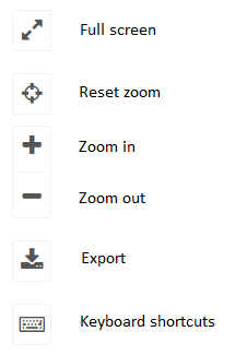
Fig. 503 Viewing tools
Full screen: it allows you to enter full screen mode, in which the edit zone will be expanded to your screen’s maximum available space. This will allow you to focus on the diagram’s creation and configuration without visual interruptions. To exit full screen mode, press the “Esc” key or click the Exit full screen buton (Fig. 504).
Reset zoom: it places the zoom level back where it initially was.
Zoom in: it increases zoom.
Zoom out: it decreases zoom.
Export diagram: it allows you to export the created diagram design. When you click the button you will have the options to export the diagram image, by selecting the “Export diagram” option, or its BPMN file, by selecting the “Export document” action, as Fig. 505 shows.
Keyboard shortcuts: it shows a popup message that indicates all the available keyboard shortcuts, as Fig. 506 shows.

Fig. 504 Exit full screen
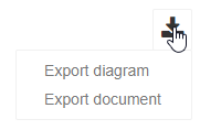
Fig. 505 Export options
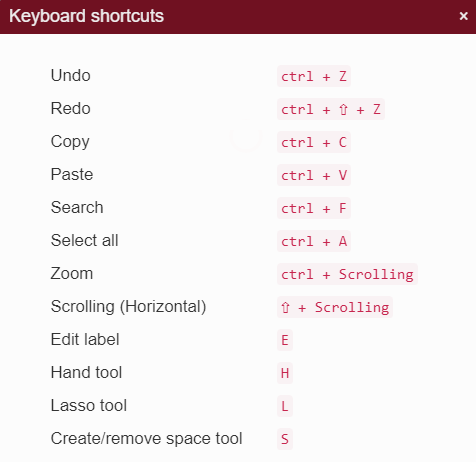
Fig. 506 Keyboard shortcuts
Action bar
At the top of the designer is the action bar, which facilitates access to the template’s design, its data, roles, domains and other process elements. It also allows you to manage the package’s editing state and, in the case of templates, it also offers the option to publish and test them.
Graph: it shows the template’s graph, designed in BPMN notation. From this view you can edit and configure each step of the process.
Process items: these buttons allow you to directly access the data, roles and other elements of the template you are currently working on.
Edit: it enables the edition of the template you are currently working on.
Save: it saves the changes made to the template. If the template has already been published, the changes will impact the processes that start from it. You can choose between saving and continuing to edit or saving and finishing changes. This last option not only persists the changes made, but also releases the template so that another person can work on it.
Discard: discards all the modifications made in the template since the last time the changes were saved.
Start process: once the design version is published, you can start the process directly from Qflow Design.
Publish: publishes the template that is being edited, saving the last changes. After it is published, the process will be available to be started in Qflow Task. Each template can only have one published version, so if there is already one, it will be replaced.
Process design
To design the process, the design tools are used to add elements and connect them. Each element has properties that can also be modified from the design.
Add an element
To add an element to the design, select it in the toolbox and drag it towards the design zone (you can also click it and then click the design zone). If you wish to add an element after another that already exists, so that it is connected to it, you can follow these steps:
Select an element.
Among the icons that appear on the right, select the one that corresponds to the type of the element that you wish to add next.
The new element also has icons to its right and you can repeat the operation with that element and the next ones.
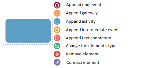
Fig. 507 Element options menu
In Fig. 508 you can see an example where, from a Start event, an activity is created.
Fig. 508 Add task after start event
Add boundary event
To add a boundary event to the design, select the intermediate event in the toolbox and drag it towards the design zone over one of the activities that allow it (Fig. 509). To see more information about boundary events and which activities allow them, see the Intermediate boundary events section.
Fig. 509 Create boundary event in user task
Change element subtype
Once you’ve added an element to the design, it may be necessary to change its subtype. This depends on the element type and whether it was added through the toolbox or through the icons that allow you to do so from the design.
If an activity is added, either from the toolbox or the design, the new activity does not have any subtype, so you must always select one. You cannot check in a design that contains an activity for which a subtype has not been selected.
To change an element’s subtype, click the subtype change icon (Fig. 507). Qflow will then show the list of subtypes that can be assigned to the selected element, select the one you wish and Qflow will assign it to the element (Fig. 510).
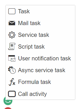
Fig. 510 Change task subtype
Delete element
To delete an element, select it and press the “Delete” key or click the Delete icon that appears when you select the element (Fig. 507).
Connect elements
To connect two elements you can use the toolbox’s connection tool: you click the icon corresponding to the tool and then click the element from which you wish the connection to exit and, without letting go of the button, move the mouse to the element with which you wish to connect the first one.
You can also use the connection icon that appears when you select an element. In this case, the element from which the connection exits is the selected one and you proceed in the same way, moving the mouse with the button clicked until the cursor is on the element to which you wish to connect the selected element.
See or modify an element’s properties
If you click an element and press the E key, you can edit the element’s name. On the other hand, if you click the button to see or modify an element’s properties, a form appears to the right of the design zone, showing its basic properties at the top (generally, the step’s name and description) and another form with advanced properties at the bottom. The properties of each element type are explained in Process design elements.
Modifying a connection
A label can be added to a connection. You can also add break points to the connection, to turn it into a polygonal line.
To add a label to a connection, double click the connection. This makes Qflow show a text box on the connection. Write the text that you wish for the label and press the “Enter” key (Fig. 511).
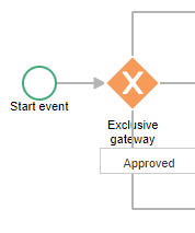
Fig. 511 Add a label to a connection
To change the connection’s shape, place the mouse cursor over the line. This makes Qflow show a small circle. Click it and, while holding the mouse button down, move the mouse. This creates a break point in the place you clicked and when you move the mouse, the line that was straight before is broken in two, forming an angle in the break point (Fig. 512).
Fig. 512 Add a break point
You can also move a connection’s segments in a horizontal or vertical way, as shown in Fig. 513.
Fig. 513 Moving a horizontal line down
Artificial intelligence assistant
Qflow allows its users to make use of the capabilities of artificial intelligence systems to support the task of designing processes.
Qflow’s artificial intelligence assistant creates designs based on a text description, which can include the general idea of the process, which steps it should have, the roles that will be a part of its operation, the data that is needed for its proper operation, and much more.
Note
The more abstract the descriptions of the process, the greater the creativity of the assistant. On the other hand, more detailed descriptions will make the assistant generate more specific processes.
To use the assistant, write a description in the text field shown in Fig. 514, and click on “Generate”.
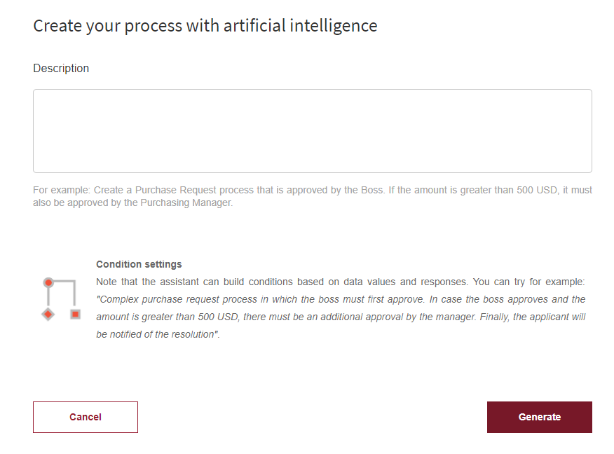
Fig. 514 AI template generator
Once the assistant is done generating the process based on the description, Qflow shows a Preview process design. We can explore this process design, its data and roles on a read only view.
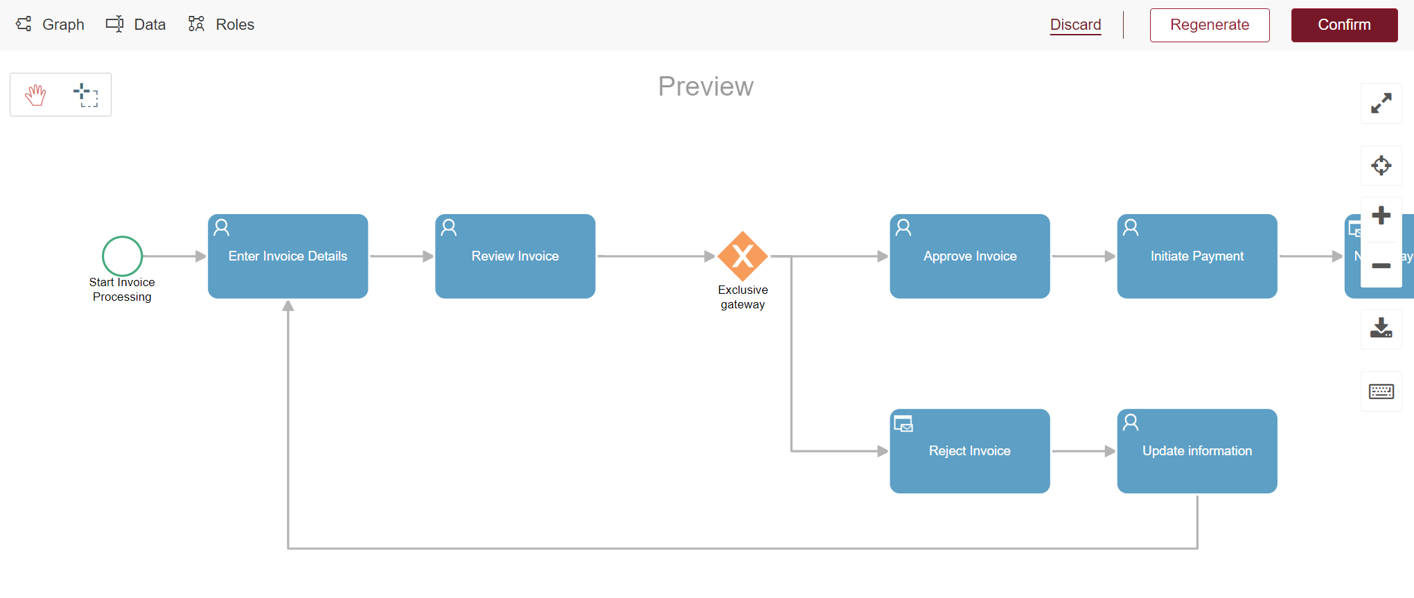
Fig. 515 Preview design
Note
The current iteration of the assistant has the ability to generate Start Events, User Tasks, User Notification Tasks, Exclusive Gateways, and End Events. As its development evolves, its ability to create processes with more types of steps will be improved.
Keep in mind that this process is not yet a part of the packages tree, and cannot be modified on this instance nor started by users.
If we wish to include the design to our process tree, be able to modify it and use it, we must Confirm it by using the button on the action bar. When confirming, Qflow will show a panel that allows setting a name and description to the process, choose in which package it will be created, and if a container subpackage should be created for it.
It is possible that the design generated by the assistant is not exactly what the user had intended. In this case, we can Regenerate it to try again and optionally, change the description of the process given to the assistant.
Lastly, the option to Discard will delete the design if you decide not to use it.
Generated processes are shown listed on the creative space menu (Fig. 479), and are stored on the browser’s memory for each user. This means that processes can be generated and left to be confirmed, regenerated or discarded at another time.
Every action that we can make on generated processes can also be found on the context menu of the creative space, which we can acces by right-clicking on each process.
Process items
To specify a process, aside from specifying a design, you can also define other items, which can be defined in a version, a template, the package where the template is or one of its ancestors. Where to define an item depends on design considerations and the structure organization. For example, an item that is specific to a version should be defined in a version, while they are usually defined in the template to share them between versions. On the other hand, in a package you define items that are common to several processes that belong to that package (for example, if many processes use the same web service, it is convenient to store that web service’s connection data in an application parameter belonging to a package that contains all those processes).
The item types that can be defined for a process are the following:
Application data: it is data that a process handles, especially data that is necessary for user notifications or to define which paths the process will follow (other data can be stored in external databases, with the help of integrations). The process elements have access to the application data: it can be used to specify the messages that are sent to the users (see Tags). It is also useful to change the flow direction: by using gateways (see Gateways), an application datum’s value can determine that the flow should follow one path instead of another, for instance.
Process template roles: if an activity is performed by a person, a role specifies who performs it or who can perform it. User tasks (see User task) are assigned to users through roles. They are not directly assigned to users.
Domains: they define application data types (“Number”, “Text”, “Date”) or, in more complex cases, they allow you to restrict the values that application data can have through arbitrary lists, results of queries to databases or other systems. A domain also defines how application data belonging to it is shown (for example, a date type domain is shown as a date picker).
Integrations: they define how to access external systems (for instance, services offered by the company’s existing software) to send them data or to receive data from them (for example, so that a process may save data in one of those systems’ databases or to get data from it). Service tasks use integrations.
Event handlers: they are small programs that are executed when some predefined event occurs during a process’ execution.
Validations: they are small programs that are developed to validate the data that is entered in flow forms.
Bots: like integrations, they specify interactions with external programs, with the difference that they are asynchronously executed to handle process data (the programs themselves are not defined in Qflow Design, but must be developed by a programmer).
Application parameters: they specify configuration information (database connections, service access specifications, passwords) to be used from the process.
How to work with the previously described items will now be explained. The purpose of this section is to describe these items’ properties and what they are used for. In the case of some item types’ specific aspects, how to use the user interface to define them is explained, but more general operations, common to all of them (for example, how to delete an item) are described in the Items lists section.
Application data
Application data is data that Qflow handles in processes. Each datum is associated to a domain, which is in turn associated to a data type and and a control type that determines how the datum will be shown in process forms.
Application data properties
An application datum’s properties form has the following sections.
General: it contains the name, description, domain and other options that define the datum’s behavior.
Presentation: it contains properties that define aspects of how the datum will be shown in Qflow Task.
Advanced: it allows you to define default values for the datum.
Dependencies (appears if the datum has dependencies): it allows you to define what application data is used to provide values for the domain parameters.
A list of properties for each section, with explanations, will now be shown. It is mandatory to fill the properties that appear with an asterisk (this applies for all panels). This means that, if you do not complete them, you will not be able to create the element you wish and an error message will be shown when you attempt to save.
General
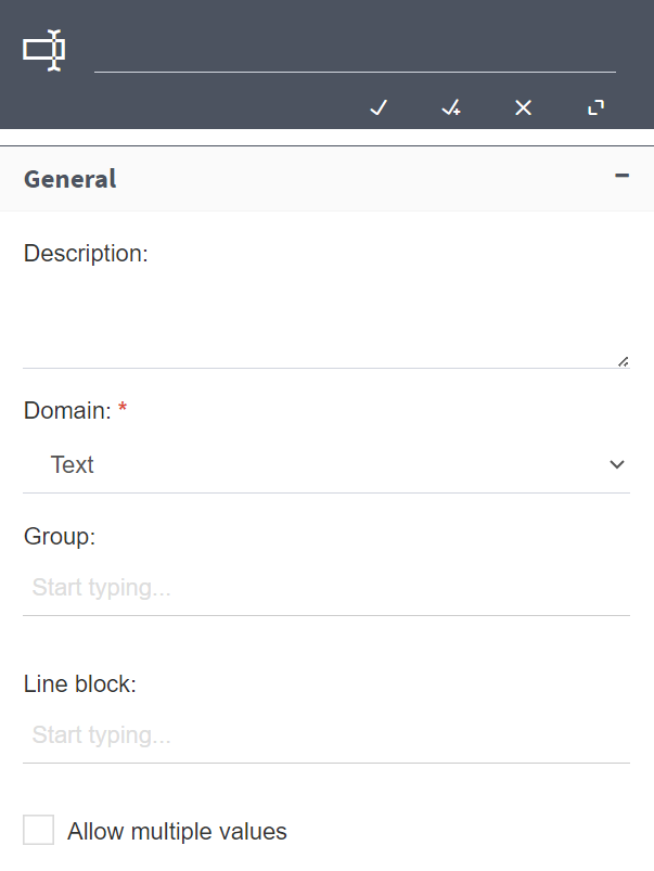
Fig. 516 Data General section
Name: it is recommended not to have repeated names between different pieces of data, given that it may cause errors.
Description is optional.
Domain: it is the data domain, which defines the type and control (the user interface element) used to show the data. The data domain can be any of the basic domains provided by Qflow, but it can also be a user-created domain that is in the same package as the data, in the parent package or one of its ancestors (see Domains for instructions on domain creation). The basic domains are:
Boolean: data of this type only has two possible values: true or false.
Date: data of this type stores dates.
Time: data of this type expresses time.
Number: data of this type stores numbers.
Text: data of this type stores text.
Text area: data of this type stores multiple-line text.
Money: data of this type can store decimal numbers.
Date time: data of this type stores date and time.
Document: data of this type stores a reference to process attachments.
Group: name of the group to which this datum will belong. To assign the datum to a group, write the group name. If the group already exists, while you type it will appear in a list underneath the name that you are typing and you will be able to select it. If it does not exist, it will be automatically created when you save the changes. Data in the same group is shown together in the data list when it is ordered by group, with the group name as a title (the list can be ordered by group by clicking the “Group” column header). This data is also shown together in Qflow Task’s forms.
Line block: it indicates the line block to which the datum belongs. The concept of a line block is explained in Line blocks. To be in a line, the datum must be a multi-valued one.
Allow multiple values: if this option is checked, the datum can have many values. It is a data set instead of a datum.
Presentation
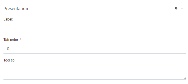
Fig. 517 Data Presentation section
Label: it is the name with which the datum will be shown in Qflow Task. The users will not see the datum’s name, but its label. The label can have symbols that are not allowed in the datum’s name.
Tab order: it indicates the order in which data will be shown in Qflow Task’s default forms. For example, the datum with tab order value 0 will be shown first; the one with value 1 will be shown second and so on. In the case of line block data, in which each datum corresponds to a table column, the datum with index 0 will occupy the first column, the one with index 1 the second one and so forth.
Tool tip: it is the text that is shown when, in Qflow Task, you view the help for the data group to which it belongs.
Advanced
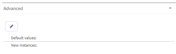
Fig. 518 Data Advanced section
Default values: a list with the values with which the datum will begin when a process is started. If the datum does not accept multiple values, only one default value can be defined.
New instances: if the datum accepts multiple values, in Qflow Task, when a user clicks to add a value the added value will be the one indicated in this property.
Dependencies
The Dependencies section only appears if the application datum is associated to a domain that accesses a database, web service or SharePoint list, and which has input or output parameters (check the Data sources section to see how those domains are configured).
If a domain has input parameters, you must specify from what application data the values will be taken that will be used in those input parameters. This is done in the “Dependencies” section: an application datum is associated to each of the domain’s input parameters.
The same thing happens with the output parameters: when a domain has output parameters, you must specify in what application data the ouput parameters’ values will be stored. This is also done in the “Dependencies” section, by associating an application datum to each output parameter.
The “Dependencies” section shows the domain’s parameters in a table with three columns. In the first column the parameter names are shown. In the second one you can see the type: input or output, indicated by an icon. In the third one you must choose, for each parameter, which application datum you wish to associate to it.
Fig. 519 shows the dependencies section for a datum from the “Customer” domain. This domain has an input parameter (“id”) and four output parameters (the rest). In the “Application data” column you can select, for each parameter, an application datum. In this case, the “Id” application datum was selected for the “id” parameter. This means that in order to obtain data, the domain will use the value of the “Id” application datum. For example, when a user logs in to Qflow Task to respond to a task, they will be able to enter a value for the “Id” datum and when they do, the domain will obtain data using the entered identifier.
The domain also has output parameters associated to application data. For example, the “name” parameter is associated to the “Name” application datum, so when the data is obtained, the value of the “name” parameter will be loaded in the “Name” datum.
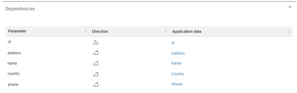
Fig. 519 Application data dependencies
Line blocks
When a data set belongs to a line block, that data is shown grouped under the same label in Qflow Task. For a datum to belong to a line block, it must accept multiple values.
In Qflow Task, a block’s data is shown as a table: each row in the table has as many values as there is data in the block. For example, the Employees row (Fig. 520) has three pieces of data. This block is shown in the website as a table with three columns, one for each piece of data: Address, Name and Phone number. See Task’s manual for details on how a user interacts with line blocks.
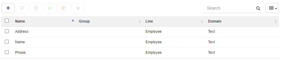
Fig. 520 Line block data
Visibility: which data can be seen and modified in each interaction with a process
By default, users cannot see or modify application data when they start a process or during its execution. To allow a user to see or modify application data, configure its visibility in the steps where you wish for it to be seen or modified. It is also possible to configure it in the flow’s form and edit form. The data visibility also specifies, for the case of line block data and multi-valued data, if users can add or delete instances, as well as the limits to the number of instances than can exist. To obtain information about it, check the Data, roles, attachments and comments visibility section.
Process template roles
When Qflow must send a message belonging to the task, it will verify which users are performing that role and send the message to those users.
Installations and workspaces will have by default two roles included in the root package, one representing the user who starts the flow, and one representing the supervisor of said user. As they belong to the root package, they can be used in any of the templates or template versions that are created.
Role properties
A role’s form has the following sections:
General
Restrictions: it allows you to restrict who can be a role member.
Presentation: it allows you to specify how the role is shown in Qflow Task.
General
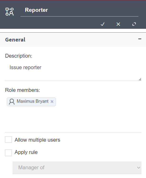
Fig. 521 Role General section
The “General” section has the following properties:
Name: it is recommended not to have repeated names among roles, given that it may cause errors.
Description
Role members: a list of users, roles, system roles, groups and work queues that perform the role. There can only be more than one member if the role allows multiple users. For a work queue or a group to be able to be a role member, it is also necessary for the role to allow multiple users. To add a member, start typing their name where it says “Start typing a user…” and when you see the role you want in the list that appears, select it.
Allow multiple users: if this option is checked, the role can have many members or members that have many users (for example, groups).
Apply rule: it applies a rule that determines who the role members are.
Managed by: if this rule is applied, the role members are not the ones in the member list, but those users who are managed by them. For instance, user Smith is a manager of Brown and Jones. If Smith is in the list and the “Managed by” rule is applied, the role members will be Brown and Jones, not Smith. Additionally, the rule is applied at the time the role is used. This means that, if at the time the role is defined, Brown is managed by Smith, but shortly before a process sends a task to that role somebody changes their manager, they will not receive the task, because they will no longer be a member of the role.
Manager of: if this rule is applied, the members will be the managers of the ones included in the member list.
User with least tasks: if this rule is applied, Qflow considers the user who performs the role to be the user with the least pending tasks at the time of using the role. For instance, let us suppose that the role has three users as members: Smith, Brown and Jones. A task is addressed to that role and uses the “User with least tasks” rule. If when the process reaches that task, Smith is, of the three users, the one with the least pending tasks, the task will be assigned to Smith.
Direct manager of: if this rule is applied, Qflow considers each direct manager of the members that have been added to be a user that fulfills that role. A direct manager of a user is the one assigned as manager in the organizational node where the user is located.
User with least tasks for template: if this rule is applied, Qflow considers the user who fulfills that role to be the user who has the least pending tasks belonging to flows from the same template. For example, let us suppose that the role has Smith, Brown and Jones as members. A task is addressed to that role, which uses the “User with least tasks for template” rule. The process template is called “Approvals”. If when the flow reaches the mentioned task, Smith is the one who has the least pending tasks in flows from the “Approvals” template of the three users, then the task will be assigned to Smith. Note that this rule is similar to “User with least tasks”, except that not all tasks that each user has pending in the system are counted, but only the ones from the process template to which the task belongs.
Sequential distribution (Round Robin): if this rule is applied, Qflow will take the set of users defined in the role, and assign them sequentially, starting with one and each time the role is assigned in a task, it changes to the next member, even within the same process. Once all the members of the role have been covered, we start again with the first one and repeat the same order.
Restrictions
The “Restrictions” section (Fig. 522) allows you to restrict the users that can be selected for this role. If you wish to restrict who can perform that role to a user list, mark the “Restrict role member selection” option. Then you will be able to add restrictions to the list. Only users that comply with the specified rules will be able to perform the role. To add a restriction, click the button with the “+” symbol. This adds a row.
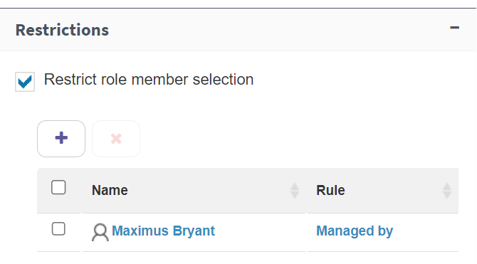
Fig. 522 Restrictions
Click the “Name” column in the selected row to write the name of the member (user, group, node or work queue) you wish to restrict the role to. You can also select a rule by clicking the “Rule” column in the same row. The rule indicates how that member is used to define the restriction. For instance, the easiest possible restriction is to select a user as a member and use the “None” rule. In this case the restriction will indicate that the selected user can perform the role, but not other users (unless some other restriction indicates that they can). The possible rules are:
None: the selected role member can perform the role.
Manager of: the managers of the selected role member can perform the role.
Managed by: the users who are managed by the selected role member can perform the role.
Members of: the members of the selected role member can perform the role. For example, if the selected role member is a group, the rule references the members of that group. Naturally, this rule cannot be applied to a user.
Visualizers of: this rule is only valid if the role member is a work queue. It means that users who have visualization permissions in that work queue can perform the role.
Actuators of: this rule is only valid if the role member is a work queue. It means that users who have actuation permissions in that work queue can perform the role.
Presentation

Fig. 523 Role Presentation section
Label: it is the name with which the role will be shown in Qflow Task. Users will not see the role name, but the label. The label can have symbols that are not allowed in the role name.
Tab order: it indicates the order in which roles will be shown. For example, the role with value 0 will be shown first; the one with value 1 will be shown second and so forth.
Suggestion: it is the text that is shown when, in Qflow Task, you view the roles group’s help.
Pre-created roles
Qflow includes two roles that are commonly defined to use in processes. Given that these roles are defined on the root package, they can be used in any package, template or version that we create.
Flow starter user: it takes the value of the user that starts the flow from its start form in Qflow Task.
Flow starter manager: it takes the value of the user that manages the user that starts the flow from its start form in Qflow Task.
Visibility: which roles can be seen and modified in each interaction with a process
By default, users cannot see or modify a process’ roles during its start or execution. To allow users to see or modify a process’ roles, configure the roles visibility in the design elements where you wish for them to be seen or modified. The roles visibility also specifies, for those that accept multiple values, if users can add or remove members, and sets limits to the number of members that users can add or remove.
For information on how to configure the visibility, check Data, roles, attachments and comments visibility.
Domains
A datum’s domain specifies the set of values that the datum can take and is associated to a data type. For example, if a datum must only store values corresponding to dates, that datum’s domain is the set of all possible dates. In Qflow, each application datum is associated to a domain, which is in turn associated to a data type.
The domain’s data type determines the application datum’s type. For example, if an application datum is associated to the “Date” domain, its value must be a date. Thus, through its data type, the domain defines the values that the data associated to it can take. These values can be limited further if the domain is associated with an operation that defines a more restricted set of values (for example, the result of a database query).
A domain also defines the way in which its data will be shown and edited in Qflow Task. For instance, data from the “Date” domain is shown through a control (form item) that allows you to select a date (i.e. a date picker).
Qflow offers a set of basic domains, but it is possible to define additional domains.
Qflow’s basic domains
Qflow’s basic domains are the following:
Boolean: it is associated to the “True”/“False” data type and the “Check Box” control.
Date: it is associated to the “Date” data type and the “Date picker” control.
Number: it is associated to the “Number” data type and the “Text box” control.
Text: it is associated to the “Text” data type and the “Text box” control.
Text area: it is associated to the “Text” data type and the “Text area” control.
Money: it is associated to the “Number” data type and the “Text box” control.
Time: it is associated to the “Time” data type and the “Time picker” control.
Date time: it is associated to the “Date” data type and the “DateTime picker” control.
Document: it is associated to the “Text” data type and the “Document” control.
For more information on domains’ control types, check the Control types section.
Domain properties
A domain’s properties form has the following sections:
General
Properties
General
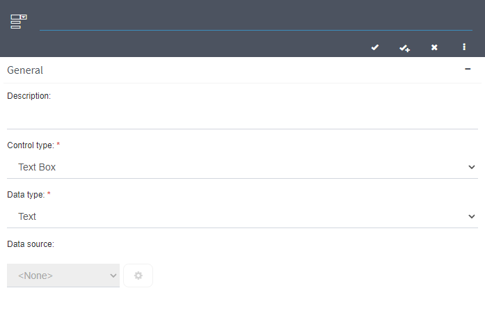
Fig. 524 Domain General section
Name
Description
Control type: it is the control type that will be used to enter or show values of that domain’s data. A control is a user interface element, like a list, a text box or a button, that lets the user interact with the system. Further down each control type is described in greater detail.
Data type: it is the type of the values that the application data associated to the domain will take. Not all types are compatible with all controls. For instance, if the control is a date picker, the data type must obligatorily be Date. The data types are the following:
Text
Number
True/False
Date
Time
Data source: this option is only valid for some control types. It allows you to select a data source type to then specify how to obtain data from a data source of the specified type. Once you have selected the data source type, click the configuration button (Fig. 525) to specify how data is obtained. The available data source types are:
None: leave this option in place if you do not wish for the domain to access a data source.
Database: it allows you to specify a connection to a database and a query to obtain the data.
Web service: it allows you to specify a connection to a web service and a web service method to obtain the data.
REST web service: analogous to the previous one, but for a REST type web service.
SharePoint list: it allows you to specify a SharePoint list and a CAML query to obtain the data.
SharePoint Online: same as the normal SharePoint list, but for SharePoint Online lists.
List: it allows you to manually define it, enumerating the set of possible values through a list. Each list element has a key and a text associated to it.
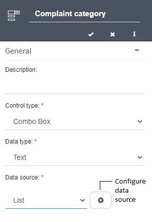
Fig. 525 Domain properties form
Properties
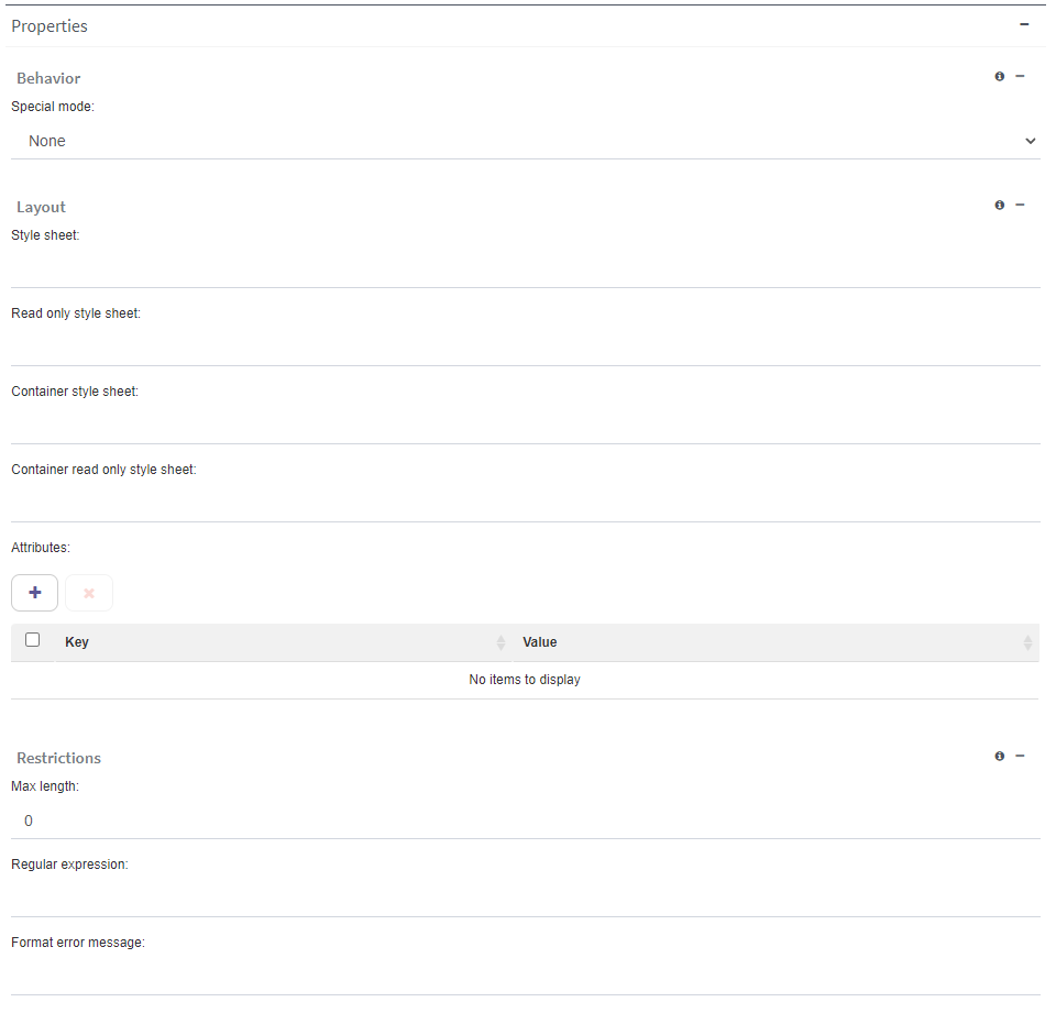
Fig. 526 Domain Properties section
In “Properties” you can specify a set of style sheets to apply to the control that is used to show the domain data in Qflow Task.
Behavior:
Add empty option to the Combo Box: it allows you to add an option to a domain with the “Combo Box” control type that, when selected in a form, indicates that none of the domain’s values were selected.
Special mode: this property is only available for domains with the “Text box” control type and it allows you to add an additional property to the control with which the domain data is shown. This property is an HTML5 characteristic that lets you take advantage of this standard’s validation and semantics features. The special modes available are:
E-mail
Phone
Number
Password
AM/PM format: this property is for domains that use the “Time” data type or “DateTime picker” control type. If its value is “True”, the domain data will be shown in the AM/PM format (“one in the afternoon” - 1:00 PM). Otherwise, it will be shown in 24 hour format (“one in the afternoon” - 13:00).
Display seconds: this property is for domains that use the “Time” data type. If its value is “True”, the domain data will be shown with seconds. Otherwise, seconds will not be shown.
Layout:
Style sheet: name of the styles class to show in all cases.
Read only style sheet: name of the styles class to show when a datum has read-only visibility.
Container style sheet: name of the styles class of the element that contains the control.
Container read only style sheet: name of the styles class of the element that contains the control when a datum has read-only visibility.
Attributes: set of name-value pairs of HTML attributes that Qflow will add to the control that shows the domain data. Use the button with the “+” symbol to add a row to the attribute list and then modify the key (attribute name) and the value to specify the attribute.
Direction: this property is only available for domains whose control type is “Radio button” or “Check Box list”. It allows you to specify if these controls’ options should be shown one next to the other (“Horizontal”, the default option) or one on top of another (“Vertical”).
Restrictions:
Regular expression: this property only exists when the domain data type is “Text” or “Document”. It allows you to specify a regular expression to validate the text that is written or the name of the file that is being uploaded. If a user enters a text that does not match the regular expression, Qflow will show them the error message specified in the “Format error message” property.
Format error message: the text of the error message that will be shown to the user if they enter a value that does not match the regular expression defined in the “Regular expression” property.
Comparison operator: it allows you to specify the operator that will be used to compare a user-inputted date with the date specified in “Date to compare”.
Date to compare: this property only exists when the domain data type is “Date”. It allows you to specify a date with which Qflow, when validating the domain’s application data values, will compare the user-inputted dates. The “Comparison operator” property allows you to specify what comparison will be made.
Max length: this property only exists when the domain data type is “Text”. It allows you to specify a maximum length for the values of the data associated to that domain.
Max value: this property only exists when the domain data type is “Number”. It allows you to specify a maximum value for the values of the data associated to that domain.
Min value: this property only exists when the domain data type is “Number”. It allows you to specify a minimum value for the values of the data associated to that domain.
Data sources
This section explains how to configure the data source access for each type. The configuration usually has two parts: the source connection specification and the specification of which data it takes (the query). The exception to this are the List sources, for which you directly specify the list elements.
Connection configuration
To specify the connection, there are always two options (Fig. 527):
Use application parameter: in this case, select the application parameter that contains the connection specification.
Define in data source configuration: in this case, click the configuration button.
It is recommended to use an application parameter (for information on how to define application parameters, see Application parameters).
If you decide to specify the data location in the data source configuration, you must complete the same connection data that you would if you were defining an application parameter.
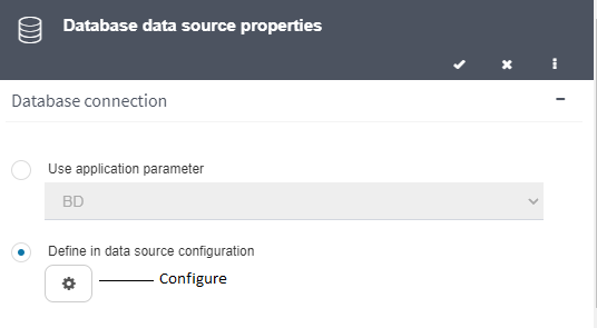
Fig. 527 Data source connection options
Database query definition
Defining a database query requires you to know how to use SQL.
Fig. 528 shows the form in which a database query is defined. To define the query, you can write it directly in SQL or you can use the query builder (Fig. 529). The first column in the “Select” sentence must be the column that contains the data key. The second column must be the one that contains the description (for example: “Select Id, Name From Customers”). More columns can be included. In that case, to use the data that comes in the additional columns, it must be associated to output parameters. Under the query, there is a section dedicated to these parameters, which is explained further down.
Queries can have input parameters. To create an input parameter, click the “+” button in the table that appears in the upper half of Fig. 528. “Test value” is the value that said parameter will have to test the query. You can edit and delete existing parameters. To insert an input parameter in the query, click the button indicated in Fig. 528.
The input parameters are represented in the query with braces. In Fig. 528, there is an input parameter called “Country”.
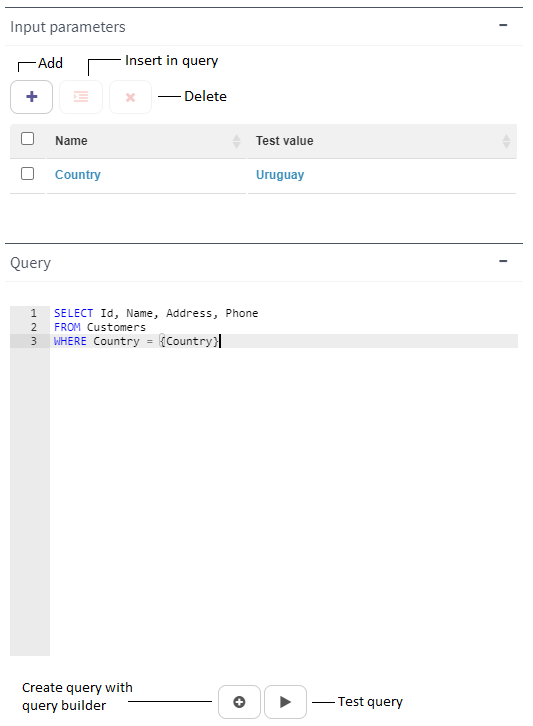
Fig. 528 Query definition
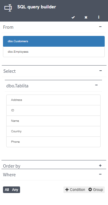
Fig. 529 Query builder
The query builder makes the query definition easier by showing the names of the available tables. Additionally, once the tables in the “From” section of the query have been selected, the available columns appear to be selected in the “Select” section. In “Order by” the columns that you wish to use to order the result are added and in “Where” the filter conditions are defined through an interface like the one used to define gateway conditions (see Conditions specification).
Test query
Before saving the domain’s configuration, you must test the query. To do that, click the Test query button (Fig. 528, “Test query”). If the query works, Qflow shows the result of executing it.
Output parameters
To define output parameters, it is necessary to test the query by clicking on the right button as shown in Fig. 528. Instead of the query form, the columns obtained as a result of said query will be shown. Close this result and you will return to the previous form, but now, as you can see in Fig. 530, the parameters are enabled and can be edited. Click the name in blue to edit it.
The names you write are the ones you will see when you configure some application data to store these parameters’ values in it. Parameters are associated to application data in that data’s properties form, in the “Dependencies” section (see Dependencies).
Once the query has been defined, click the Save button to save it.
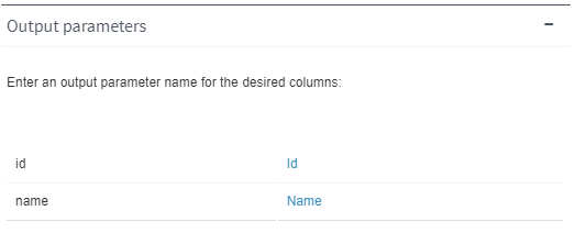
Fig. 530 Output parameters
SOAP web service query definition
Once you have specified the connection to a SOAP web service (see Connection configuration), you must click the Load button (see Fig. 531) to load the list of methods from that web service. After that, where it says “Select web method”, select the method you wish to use for the domain. When you select the method, its parameters are loaded. The method parameters are associated to input parameters. The selected method must return a list of simple objects.
Input parameters
A fixed value can be assigned to each parameter. If the control type is Lookup, Item selector or Combo box, that value can also be set to a parameter. To do that, in the parameters table (Fig. 531) you must select each parameter’s type. There are two parameter types:
Custom: a custom parameter works like domain parameters that obtain their data from a database: when an application datum for that domain is defined, another application datum is defined as a parameter (see Dependencies). For a parameter of this type, enter a name (Fig. 531).
System: a system parameter is used with a web service method specially developed to interact with the domain in such a way that the query is more efficient. For example, instead of a Lookup that retrieves all of a table’s elements and only filters the data by key in the client code, you can develop a method that obtains the key as a parameter and returns only the record that has the key that was sent. System parameters are not associated to application data. Qflow determines how to invoke a method based on which system parameters are defined. There are four system parameter types:
Filter by key: it is meant to be used with a method that receives a key (identifier) as a parameter. Qflow uses it, for example, with Lookup type controls. An example of a method to use with this parameter is GetCustomer(string key).
Filter by text: it is meant to be used with a method that receives a description as a parameter. Qflow uses it, for example, to send the text that was entered in the item selector. An example of a method to use with this parameter is GetCustomer(string filter).
Maximum quantity of items: it is useful if the web service method receives a parameter (of “int” type) that indicates the maximum number of elements that it must return. An example is GetCustomer(string filter, bool startsWith, int maxQuant). Another example is GetCustomer(string key, int maxQuant).
Column mapping and output parameters
A data source query for a domain must return at least two columns: one for the key and one for the description of the returned entities. If the source is of database type, the first returned column is taken as the key and the second one as the description. But if the source is a web service, there are no columns but object properties and there is no way to determine which of the properties corresponds to the key and which to the description. To do that, the column mapping is used.
Column mapping consists of defining columns and associating each of them to an object property. The first two columns are used for the key and description respectively. Additional columns are optional and can be associated to output parameters (see further down).
By default, the mapping table has all the properties mapped to a column name. If you wish to change a name, click the text corresponding to “Column name” to input the column name and afterwards press “Enter”. If you wish to remove a mapping, click the row and then the “Clean mapping” button (indicated in Fig. 531). You can also change the mapping order with the corresponding buttons.
After this, each defined column is associated to an output parameter through the “Output parameters” button (analogous to a database query): each column is assigned a parameter name. Both input and output parameters are associated to application data through the “Dependencies” section of application data belonging to the domain (see Dependencies).
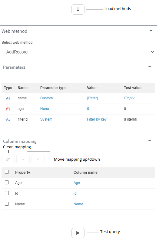
Fig. 531 Web service query
REST web service query definition
Once the connection to a REST web service has been specified (see Connection configuration), the action to be performed must be specified, which is a URL corresponding to the web service you wish to query (Fig. 532). After that the required HTTP method must be selected (GET, POST or PUT).
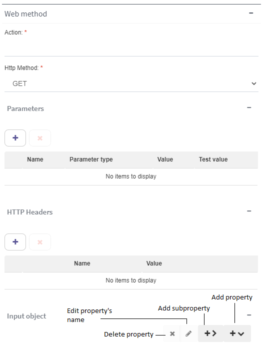
Fig. 532 REST web service query
Input parameters have the same type as in SOAP web services (see the Input parameters section), but unlike those, they are not automatically loaded. Instead, the user must enter them manually. You can give them a name and value (both must be unique) aside from the type. These parameters are used to load values in the headers, as is explained below, and the input object, as is explained in Input object.
HTTP headers
HTTP headers, which are key-value pairs, can be specified to be sent in the request. The key is a text and the value must be a parameter of type “None” or “Custom” that has been defined in the “Parameters” section table.
Input object
The input object is of JSON type and is an object with properties. These properties can be values (that are taken from the input parameters) or subproperties, which in turn have more values.
To create a new property, click the button indicated in Fig. 532. This will open a menu as in Fig. 533.
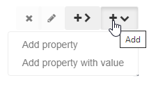
Fig. 533 Properties menu
If you wish to add a property with subproperties, select the “Add property” option (later you will be able to add subproperties to the main property). Otherwise, select the “Add property with value” option. This will allow you to give a value to the property from an input parameter. Analogous options are shown when you click the “Add sub property” button.
Fig. 534 shows an example of a tree with properties and subproperties.
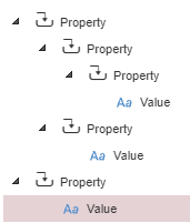
Fig. 534 Properties tree
To edit the name of a property or subproperty, you can use the button indicated in Fig. 532 or press F2. Remember that, when the query is made, the properties that are in the same tree level must have different names. You can also delete a property by using the corresponding button (Fig. 532). These two options are also shown in a context menu if you right-click the property.
Once your tree structure has been created, you must enter the necessary values. All values must be assigned a parameter; if you wish to send a property with an empty value, create a parameter whose value is empty (it must not be of System type). To assign a value to a parameter, right-click the value. This will open a context menu like Fig. 535 shows.
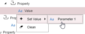
Fig. 535 Values context menu
If you place the cursor on the “Set value” option, on the right a submenu will be displayed with all existing parameters. Click the one you wish to assign and the value will be shown with that parameter’s name. You can assign the same parameter to more than one value. The Clean button allows you to remove the parameter that is currently assigned to the value.
In Fig. 536 an example of a final result is shown.
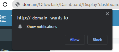
Fig. 536 Tree with loaded properties and parameters
Once your input object has been created, you must test the query, like in SOAP web services, using the button to this end (analogous to Fig. 531). The query result must be an array of JSON objects. Since a JSON object could potentially have several levels of subproperties, there is a limit to the shown depth. This can be seen in Fig. 537, where fields with an information symbol are those that have more subproperties, but they are not shown.

Fig. 537 Query result with an unsupported depth level
After the query has been tested, the Column mapping table will be loaded with the discovered properties. You can then proceed to create the corresponding mappings and load the output parameters as was explained in the Column mapping and output parameters section.
Control types
This section explains the control types that can be used by data domains. The possible control types are:
Text area
An area where several lines of text can be written. It is ideal for data whose values are long texts.

Fig. 538 Text area
Check Box
A square box to check or uncheck an option. It is only useful for true/false type data.

Fig. 539 Checkbox
Combo Box
A list that, when it is expanded, shows options for possible data values. It is appropriate when the user must select one of several options.
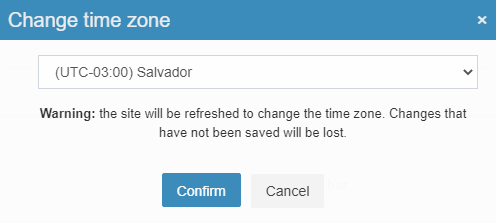
Fig. 540 Combo Box
Text box autocomplete
A text box autocomplete allows a user to write part of a text and it shows them a list of values whose texts begin with what the user wrote. Those values are obtained from some data source. For example, let us suppose that a user has to select the name of a product among the products a business offers. If the business has many products, it may not be so practical to have a combo box. It may be more practical for the user to start typing the product name and for a list to progressively show the products whose names are similar to what the user is typing, until they are finally so few that the user can find the one they wish easily and select it.
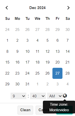
Fig. 541 Text box autocomplete
Text box
A common text box with a single line (like the text box where the name of a domain is written).

Fig. 542 Text box
Rich text box
Similar to the text area, but it allows you to modify the text’s format properties such as using bold, italics, aligning the text, adding lists or other elements.
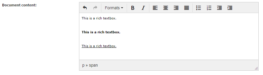
Fig. 543 Rich text box
Document
A datum from a domain that uses this control type is shown, if it is editable, as a control to upload files (otherwise, only the data value is shown). When a user uploads a file using this control, the file is attached to the process and additionally, in the data value the new attachment identifier, version and path of the uploaded file are stored, separated by a semicolon (“;”). This way, the user not only attaches a file, but it is associated to a datum that gives meaning to the file. For example, you can require the user to upload a resume by having a “Curriculum Vitae” control.
For a user to be able to upload a file, not only must the datum be editable, but the visibility must allow them to add files (see Attachment visibility).

Fig. 544 “Document” control type, modifiable
Label
A control that shows a text, but does not allow you to modify it, even when the data visibility defines that you have permission to edit the data in the step you are responding to or the start event.
Fig. 545 Label
Hyperlink
A control that, when clicked, navigates to a web page. It is useful when the data represents web addresses.
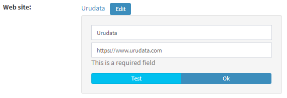
Fig. 546 A hyperlink with its edit window
Check box list
A set of check boxes. It is useful when you wish to present the user with a list of options and the user can select several of them. The options’ texts are copied in the data value one after the other, separated by line breaks (only text type domains accept this control type).
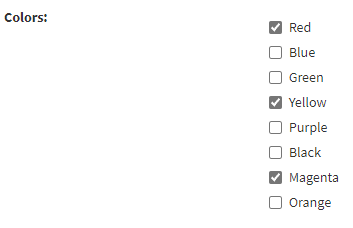
Fig. 547 Check boxes list
Lookup
A control that allows you to obtain, from an identifier, a value belonging to said identifier. It can be taken from a database, a list or a web service. The user types the identifier in a text box and Qflow shows the value corresponding to that identifier.
Fig. 548 Lookup
Radio button
It is similar to a check box, but when there are several “radio buttons” in the same area, only one of them can be checked. Thus, when one is checked, the others are automatically unchecked.
Fig. 549 Radio Button
DateTime picker
A combination of a date picker and a time picker. If you place the mouse over the world symbol, you will see the user’s preferred timezone.
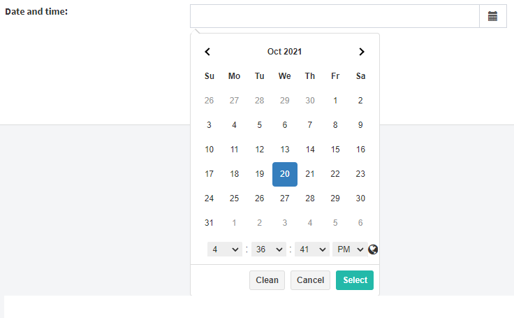
Fig. 550 DateTime picker
Date picker
A control that displays a calendar to select a date.
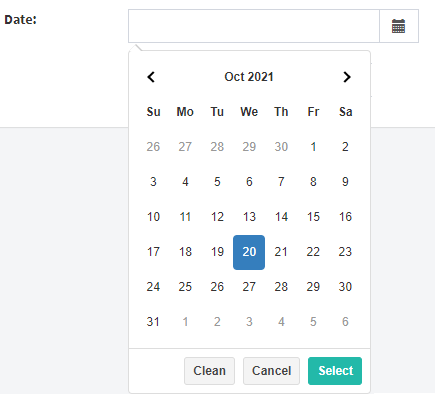
Fig. 551 Date picker
Time picker
It is a control that allows you to enter times and automatically validates them.
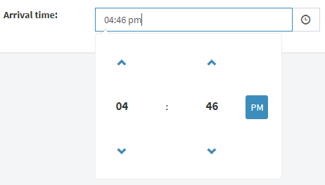
Fig. 552 Time picker
Item selector
A list that allows you to select a particular element from a set with a large number of elements (for example, taken from a database). The elements are shown in a list and Qflow filters them as the user types the name of the sought element.
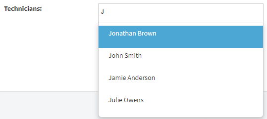
Fig. 553 Item selector
Integrations
Integrations allow Qflow to interact with other systems through the execution of software component operations. A process can execute an integration’s operations through a service activity (see Service task).
An integration’s definition requires technical IT knowledge. That is why Qflow separates an integration’s definition from its use.
To define an integration, one or more operations must be defined. An operation is a set of calls to a component which is external to Qflow. For example, in an integration with a web service, it is a set of calls to that web service’s methods. One of the operations is selected as the production one and it is the one that is executed when the integration is called.
Integration properties
An integration’s properties form has the following sections:
General: aside from allowing you to specify the integration’s name and description, it allows you to select the production operation.
Parameters: it allows you to define the integration’s parameters. Parameters let the process send data to the integration when it calls said integration, as well as receive data from it when the integration finishes its execution.
Operations: it allows you to define the integration’s operations. An integration operation that accesses a web service, for example, is specified through the web service’s URL, the name of the method that must be invoked and the parameters that are passed to that method.
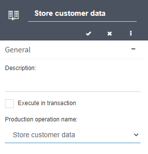
Fig. 554 Integration properties
General
“General” section properties:
Description
Execute in transaction: it allows you to specify whether the operation should be executed in a transaction, i.e. in a context in which many operations are executed and, if at least one of them fails, then they are all cancelled and rolled back. This is only possible with some operations (for example, database operations). TECHNICAL NOTE: this option is implemented by executing the integration code inside a TransactionScope.
Production operation name: it indicates which of the operations defined in the integration is the one that will be used (see further down how to define operations; initially there are no defined operations and it is therefore not possible to select one). To select the production operation, click the selected option (it can be “None”) and choose an operation from the list that Qflow shows you.
Parameters
The parameters section shows a table (which is initially empty) with the integration’s parameters. Parameters allow you to send data to the operation that is being executed or to receive data from the result of executing the operation. For example, if the integration invokes a method from a web service that has two parameters and returns a number, three parameters must be created: one for each method parameter and one for the result. When the integration is selected in a service task (see Service task), each integration parameter is associated to a datum or application parameter.
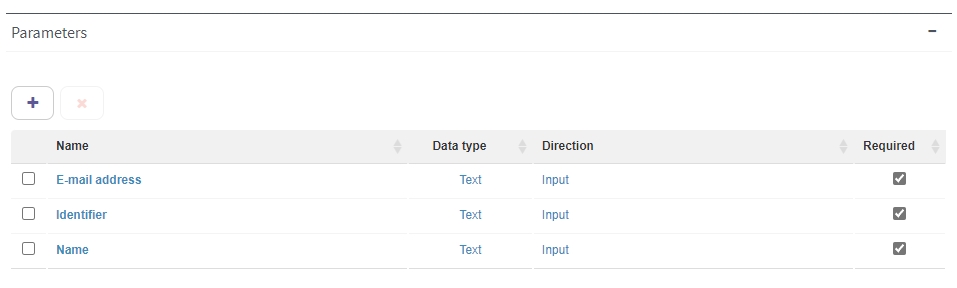
Fig. 555 Integration parameters
To add a parameter, click the “+” button. This adds a row to the table. To modify a parameter property, click its value (for instance, to modify the parameter’s name, click the text that appears in that parameter’s “Name” column).
To delete a parameter, select it and then click the delete button (✗).
A parameter’s properties are:
Name: the name that identifies the parameter.
Data type:
Text
Number
True/False: a datum with two possible values: true or false
Date
GUID: an identifier
Direction:
Input
Output
Input/Output
Required: if this option is checked, it is mandatory to associate an application datum or parameter to the parameter in the service tasks that use the integration that is being defined.
Operations
Operations are also shown in a table (Fig. 556). When an operation is added, the form of the wizard to generate it appears (Fig. 557). In the “General” section of that form the operation’s name and, optionally, description, are entered. Underneath these options are the options to add the components that Qflow must use to generate the operation. Once the components have been defined, you must click the Next button to go to the next step. At the end of the process, Qflow will generate the code that executes the operation.
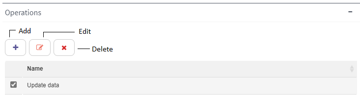
Fig. 556 Integration operations
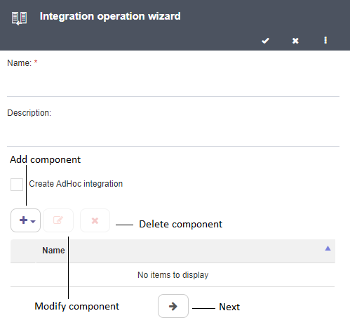
Fig. 557 Integration properties
If the “Create AdHoc operation” option is checked, it is not necessary to specify anything: an ad-hoc integration is created with code that does not execute anything. It can be used for testing or to generate an operation whose code will be hand-written later.
Otherwise, you have to specify one or more components for the operation. The available component types are:
Database: a stored procedure or a script to make queries or insert or update data (Upserts).
Rest web service: a REST web service.
SharePoint: a SharePoint list. Documents can be uploaded and elements created in a list or documents library.
SharePoint Online: similar to the previous component, but for SharePoint Online lists.
Web service: a web service.
Note
In Qflow’s OnPremise version, operations of other types can be handled: COM, Assembly (.Net component) and Qflow Assembly (.Net component which implements a Qflow predefined interface). These operations are not available in Qflow Design, but in the classic designer. Once defined, it is possible to see these operations’ code in Qflow Design.
To add a component, click the button to configure the operation (Fig. 557). A menu will then appear that allows you to select the component type. When you select the component type, a form will appear to specify the connection to the component. That form has two options:
Use an application parameter: if you mark this option, instead of specifying the connection, you can select an application parameter for Qflow to obtain the connection data from. If the list of application parameters to choose is empty, it is because there are no available application parameters for the selected component type (for example, the component type is “Database” and there are no available application parameters of “Database connection” type).
Define in data source configuration: if you mark this option, you must specify the connection data. This data is specified in the same way as if you were defining a connection in an application parameter. For instructions on how to configure a connection, check the corresponding section in Application parameters.
Database connection: See Configuring a database connection for instructions.
SharePoint list connection: see Configuring a SharePoint connection for instructions.
SharePoint list connection Online: see Configuring a SharePoint Online connection for instructions.
Web service connection: see Configuring a web service connection for instructions.
In the case of a Rest Web service type component, to configure the connection you must specify the following data:
Url: the web service URL. For example: “http://webServer/api”
Web method: supposing you wish to access the employee creation, update and deletion operations, an example would be to write “employees”.
Http method: the Http method (get, post, put or delete), which depends on which operation you wish to perform (obtaining an object, creation, update or deletion).
Headers: they allow you to specify headers for the connection with the REST web service. For the key values you must specify an integration parameter that is of input or input/output type.
Parameters: it allows you to specify the structure of the objects that are received through parameters. If the parameter is a simple value (for example, an entity’s identifier), it is enough to click on “Add property” (Fig. 559) and assign it a name by selecting it, clicking “Edit property” (Fig. 559) and entering the name. This name will later be used to associate the parameter to one of the integration’s input parameters. The “Add subproperty” button is used to specify complex objects. By combining “Add property” and “Add subproperty” you can specify an object that contains other objects. It is not necessary to include all object properties: only those to which you wish to assign values that are in the integration’s parameters.
Return object: it works in the same way as Parameters, but for the return object.
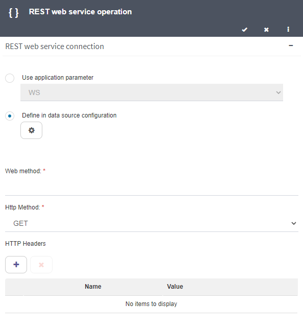
Fig. 558 Connection configuration for REST web service type integration
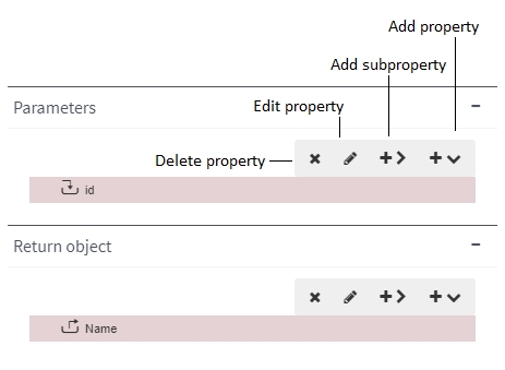
Fig. 559 Parameters and return object configuration. In this case, the object receives a simple parameter, “id”, and returns an object, from which you wish to obtain the “Name” property (the integration has an input parameter for “id” and an output parameter for “Name”).
Once a component has been specified, if you click the Save button, the component is added to the components list (Fig. 560).
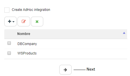
Fig. 560 Two components added to an operation
When you are done adding components, you have to specify which of these components’ operations will be executed in the operation. To move on to this stage in the operation definition, click the arrow button (Fig. 560, “Next”). The screen changes to show the available classes and methods (Fig. 561). When a class is selected, the list of available methods changes to show the methods of the selected class. The shown classes are the following:
For databases: since databases have no classes, what are shown are classes generated by Qflow to represent commands that can be sent to the database. The classes are of the following types:
[Database].Queries: these classes allow you to execute simple queries automatically generated by Qflow. When this option is selected, in the “Available methods” list an element is loaded for each database table. Each of these elements represents a “SELECT” command to retrieve the data from the corresponding table. For example, if the database has a table named “Employees”, in “Available methods” the “EmployeesQuery” “method” appears. If you also have a table called “Products”, the “ProductsQuery” method appears, etc.
[Database].StoredProcedures: these classes allow you to execute stored procedures. When this option is selected, in the “Available methods” list the database’s stored procedures are loaded.
[Database].Upserts: they allow you to execute sequences of SQL commands that are automatically generated by Qflow to update tables. When you select this option, in the “Available methods” list an element is loaded per database table. Each of these elements represents a command that inserts or updates a record in a table, according to whether the values that are passed correspond to an already existing record or not. For example, if the database has a table that is called “Employees”, in “Available methods” the “EmployeesUpsert” method appears.
For web services: the class that implements the web service’s operations is shown. If that class is selected, the methods that the web service exposes are shown.
For REST web services: the class associated to the configured component is shown, with a single method.
For SharePoint and SharePoint Online lists: the available classes correspond to the content types available for the selected list. There is also the [DynamicContentType] option, which allows you to add an element or upload a document by specifying the content type through a parameter. Once the class has been selected, two available methods usually appear: one allows you to create an element (“CreateItemX”, where X is the name of the content type selected in “AvailableClasses”). The other one allows you to upload a document (“UploadDocumentX”). In this case, aside from the parameters corresponding to the content type’s fields, there is one that must contain the path of the file that will be uploaded. If the selected class is [DynamicContentType], only the option to create an item will appear (“CreateItemDynamicContentType”).
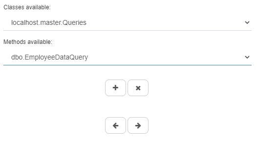
Fig. 561 Select methods
To add a method, select it and click the “+” button. When you add a method, its input and output parameters appear. Each of those parameters can be associated with one of the parameters defined for the integration. The icon next to a method parameter indicates if it is an input or output one; if you place the mouse cursor over a parameter, a label appears that reads “Input” or “Output”.
To associate a method parameter to an integration parameter, right-click where it says “Value” and select “Set value”. This makes the list of integration parameters compatible with the selected method parameter appear: the compatible parameters are those that have a convertible type and the same direction (input or output). For example, if the method’s input parameter is of “Number” type, you will be able to select the parameters that have been configured as Input or Input/Output and of “Number” type. However, if the method’s input parameter is of “Text” type, all parameters configured as Input or Input/Output will be selectable regardless of their type, since a value of any type can be converted into text. In an analogous way, if the method’s parameter is an output one of “Text” type, all parameters configured as Output or Input/Output will appear regardless of their type (Fig. 562). Select, from the list, the integration parameter that you wish to associate to the method parameter and both will be associated with each oher.
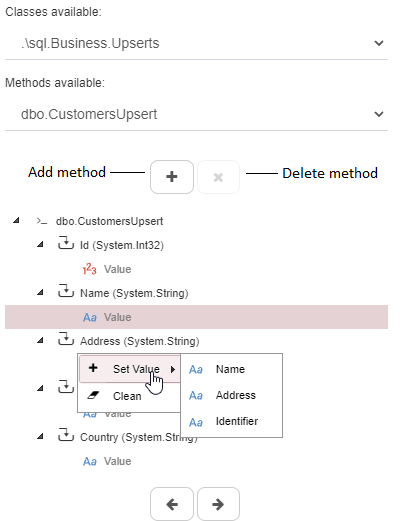
Fig. 562 Method with its parameters
An example (Fig. 563): an integration invokes a web service method, GetProductName, which receives an integer number, productId, as a parameter and returns a text.
For the integration two parameters are defined: ID, of “Number” type and Input direction, and Result, of “Text” type and Output direction. ID can only be associated to the method’s productId parameter. It cannot be associated with the method’s result because the latter is a text, while the former is a number. Additionally, ID is an input parameter, so even if the method’s result were a number, it would not be possible to associate them. The same happens with Result, which can only be associated to the method’s result.
To remove a method, select it and click the Delete method button (Fig. 562).
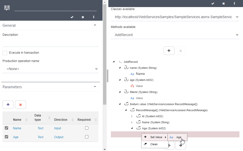
Fig. 563 Integration with two parameters and how they are associated with a method’s parameters.
Once the methods with their parameters have been specified, click the Next button again. Qflow will generate the code to call the method and save the result in the output parameters. Click the Save button to save the operation.
Once an operation has been created, you can access the generated code through the Edit button (Fig. 564).
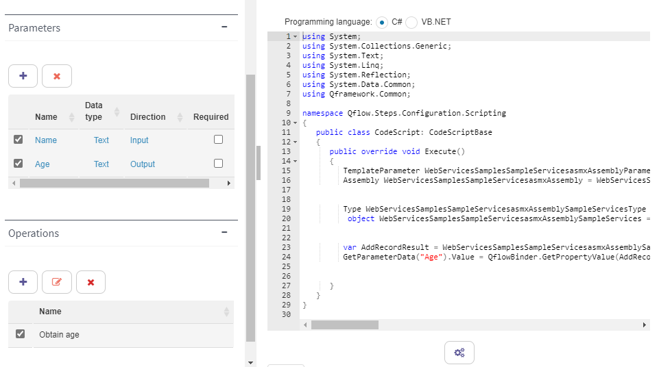
Fig. 564 Generated code for an operation
Code editor
When an operation is added to an integration, Qflow generates the code that it will execute to invoke the operation. This code can be seen and modified. The code is shown in the code editor, which is also used when editing event handlers, script tasks and validations. The Compile button allows you to compile the code. If there are errors, they are shown in the “Error” tab. In some cases, like script tasks, it is possible to execute the code with an “Execute” button. Be careful when using it: if, for example, the code modifies a database, when executing it from the editor, the database may be modified as if the code were being executed from a process. In the case of integrations, this option is not possible.
Difference in versions
The Execute button is not available in the Cloud version.
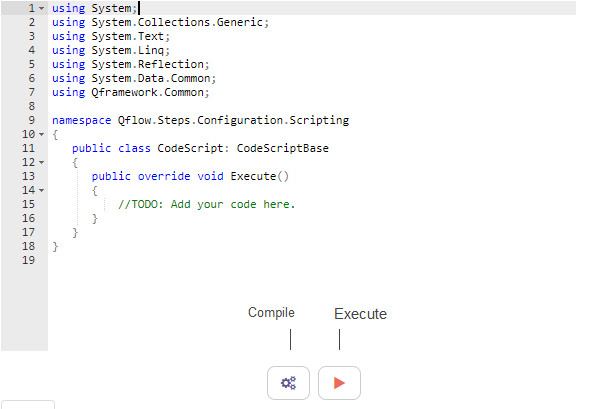
Fig. 565 Code editor
Application parameters
Application parameters are entities that allow you to separate configuration data from the entity that uses it. For example, it could happen that many process templates use the same web service from service tasks. It is uncomfortable to have to specify the service Url in each task. Additionally, if it changes, all the tasks have to be modified. Due to this it is more convenient for that data to be stored in a single place and for each web service task, instead of specifying the web service Url, to specify where that data is stored.
In the same way, there can be several different integrations that use the same web service (each invoking a different operation, for example). In that case it is also preferrable to store the web service information in a single place from which all integrations obtain the connection data. Application parameters allow you to store such data and use it in service tasks, data sources for domains that use them, integrations and as tags or parameters in other steps.
Additionally, for the connectors that Qflow offers to integrate with other tools, it is also necessary to use a connection application parameter which stores the information needed to connect with each tool.
Application parameter properties
An application parameter’s edit form allows you to define the parameter type and assign a value to it, aside from modifying its name and description. The parameter types are:
Password: the parameter value is a text that is encrypted to be saved in the database.
Text: the parameter value is a text.
Database connection: the parameter has all the necessary data to connect to a database.
Web service connection: the parameter has all the necessary data to connect to a web service (SOAP or REST).
SharePoint connection: the parameter has all the necessary data to connect to a SharePoint list.
SharePoint Online connection: the parameter has all the necessary data to connect to a SharePoint Online list.
Integration connection: the parameter has the necessary data to connect to one of the tools that Qflow offers as connectors.
To assign a value to the parameter, for example its value or the data to connect to a database, click the Configure button (Fig. 566). To configure an application parameter of “Password” or “Text” type, you must simply enter the parameter’s password or text (in the password’s case, it is entered twice).
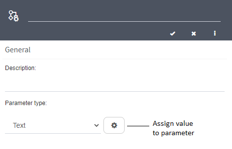
Fig. 566 Parameter properties
The configuration for database, web service and SharePoint connections is explained next.
Configuring a database connection
A database connection’s properties (Fig. 567) are the following:
Provider type: the database access provider (for example, SQL, OleDb, ODBC, Oracle provider). It depends on the type of database for which you are defining the connection.
Server: the name of the server where the database is.
Integrated security: this option is for SQL Server databases. If this option is checked, the connection is created using integrated security. Otherwise, Qflow enables the “User” and “Password” properties to enter the database user’s name and the corresponding password.
Additional parameters: it is a grid in which you can add parameters to the connection string. The grid has two columns, one for the parameter name and another one for the value. For example, if you wish to specify a 60-second timeout for the connection to an SQL Server database, you can add an additional parameter named “Connection Timeout” with a value of “60”.
Test connection: click this button to check that the entered data is correct. If the data is correct, you will be able to select a value for the “Database” property.
Database: the database to which you wish to connect.
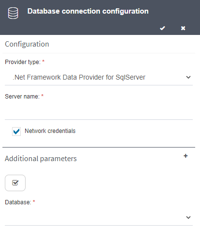
Fig. 567 Database connection configuration
Configuring a web service connection
A web service connection’s properties (Fig. 568) are the following:
Url: the web service URL (it can be SOAP or REST).
Network credentials: leave this option checked if you wish to use the credentials of the user whose account is used by Qflow’s services. If you wish to use other credentials, uncheck this option and enter the username and password you wish to use.
Test connection: if you click this button, you will be able to check if the entered URL and credentials are correct. If they are, Qflow will open the web service’s page in a new browser tab.
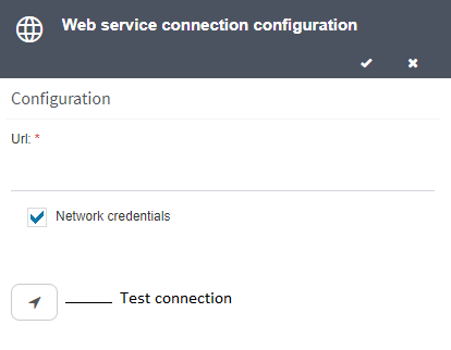
Fig. 568 Web service connection configuration
Configuring a SharePoint connection
A SharePoint connection’s properties (Fig. 569) are the following:
Site URL: the URL of the SharePoint site in which the SharePoint list you wish to access is located.
Network credentials: check this option if you wish to use the Qflow services account to connect to SharePoint or else uncheck it and enter a username and password. Use the “Test connection” button to verify that you can access the specified SharePoint site with the entered credentials. If the test is successful, you will be able to select the SharePoint list.
List: this field is enabled once you have checked that the previous data is correct, through the Test connection button. Select the SharePoint list you wish to access here.

Fig. 569 SharePoint list connection configuration
SharePoint Online list connection configuration
In a similar way to the previous configuration, with the difference that because SharePoint Online services authenticate with Office, we must enter a user name and password to create the connection. A SharePoint Online’s connection properties (Fig. 570) are the following:
Site URL: the URL of the SharePoint Online site in which the list you wish to access is located.
User name: user name used to authenticate on the SharePoint Online service.
Password: user name used to authenticate on the SharePoint Online service
List: this field is enabled once you have checked that the previous data is correct, through the Test connection button. Select the SharePoint Online list you wish to access here.

Fig. 570 SharePoint list connection configuration
Configuring an integration connection
Considering that the connection to each tool has it’s own particular configuration, the first thing that the user must choose is the tool.
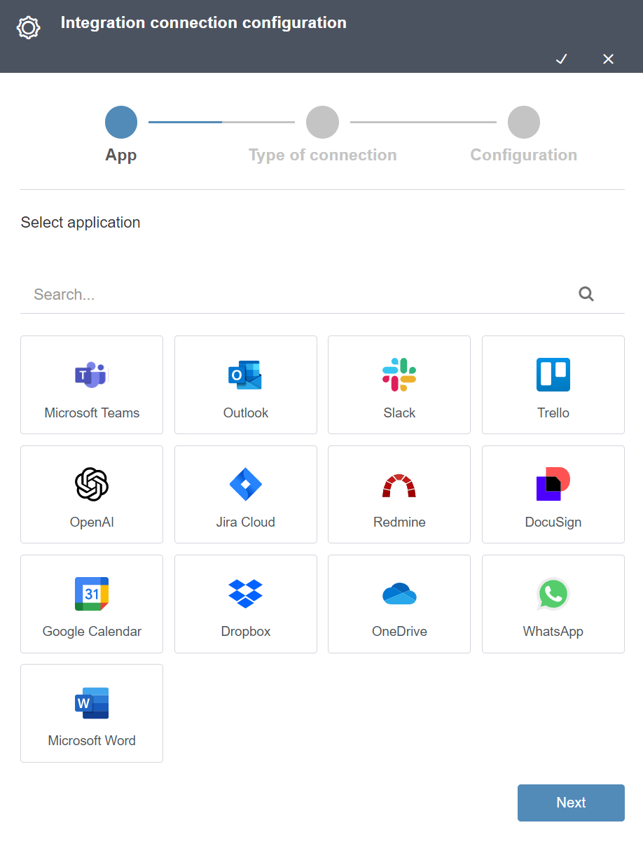
Fig. 571 Connection parameter tool selection
Once the tool has been chosen, the second step consists of selecting the connection type. Each tool can have various connection types depending on how a user can access the service they provide.
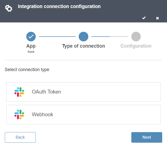
Fig. 572 Connection type selection
The final step is where the user will enter the values of the connection data. The fields to complete will depend on the connection type selected on the previous step. You can use the help tooltips available on the parameters, which will redirect you to this documentation.
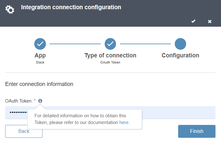
Fig. 573 Connection parameter configuration
Once saved, it is ready to use as a connection parameter in service tasks that use that same tool as a connector. For more information, you can read the specification for each connection type on the tool’s corresponding page in the connectors section.
Using an application parameter
A parameter can be used in many contexts in which it is necessary to specify the type of information that is stored in an application parameter. In a domain that uses a web service as its data source, for example, it is necessary to specify the web service URL. The user can decide to specify the URL in the domain’s own properties (“Define in data source configuration”) or use an application parameter. Application parameters can also be used in integrations. A “Text” type application parameter can be used as a tag (check the Tags section), as an external addressee to an external user task (see External task response) or as a part of gateway conditions (see Gateways). An application parameter of this type can also be associated to bot and integration parameters, in async and sync service tasks respectively. Additionally, these parameters are available in code written in script activities or Qflow type assemblies (which contain classes derived from CodeScriptBase; see the Scripting Interface manual).
Event handlers
Event handlers are small programs that Qflow executes in their context (they have access to the flow data) when a certain event occurs during a flow’s execution. The events that can trigger a handler’s execution are predefined. Defining a handler consists mainly of defining its code. Later it is associated to an event, so that when it occurs, the handler’s code is executed.
Event handler properties
An event handler’s properties form has the following sections:
General: name and description
Handler information: it allows you to define the handler’s code and determine if it is synchronous or asynchronous. This section’s properties are explained below.
Handler properties
Handler type:
Synchronous: the handler is executed in such a way that the flow waits for it and does not continue until the handler’s execution ends. The handler can modify flow data.
Asynchronous: the handler is executed in such a way that the flow does not wait for its execution to finish. The handler cannot modify flow data.
Order: it is a useful number when there is more than one handler associated to an event. In that case, handlers are executed in ascending order using that number. For example, if there are three handlers for the same event, Qflow first executes the one whose value for this property is 0, then the one with value 1 and finally the one with value 2.
Use integration: if this option is checked, the handler uses the code of an already defined integration, instead of using code written specifically for the handler. When this option is checked, the screen changes so you can select an integration and the options that allow you to write the handler’s code disappear (Fig. 574). The screen’s lower half changes to show the integration’s parameters, so you can associate application data to them, in the same way as in a service task (see Service task).
Properties if an integration is used:
Integration: a list to select the integration that contains the code that you wish to assign to the handler.
Parameters: a specification of the correspondence between application data and integration parameters. Check Integrations for details.
Properties if an integration is not used:
Language: it allows you to specify the programming language in which the handler’s code will be written. The options are C# and Visual Basic .NET.
Code: under the language options a text area appears that allows you to write the handler’s code in the selected language.
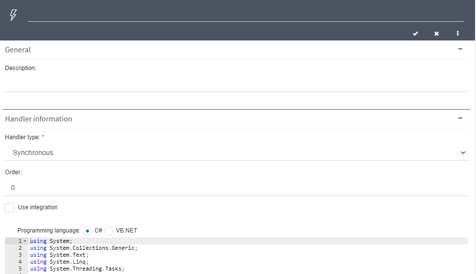
Fig. 574 Event handler’s properties
Associating an event handler with an event
For Qflow to execute an event handler, it has to be associated to an event so that when it happens, Qflow executes the handler’s code.
There are two event types:
Flow events: these events are not associated to any particular step.
Design element events: these events are associated to a user task or an asynchronous service task.
Associate a handler to a task event
To associate an event handler to a task, select it in the graph and click the properties icon to open the element’s properties form in Qflow. Then, go to the “Dev tools” tab. In that section you will find a list of events to which a handler can be assigned:
Error: it happens when an error occurs during the step’s execution.
Step finalize: it happens when the step finishes its execution.
Step start: it happens when the step’s execution starts.
Step news: it happens when there are news in the step. For example, in the case of a user task, when an addressee responds to the question. Note that the fact that there are news in a step does not necessarily imply that the flow or thread have changed their status. For example, if a user task has several addressees and the flow waits for five of them to responds before continuing, the flow will not leave the waiting status until five addressees have responded, but when the first one to respond does so, they will create news in the step.
To assign the handler to an event, select the event and click the Modify button. In the event’s properties form, select the handler and click the button with the ✓ symbol.
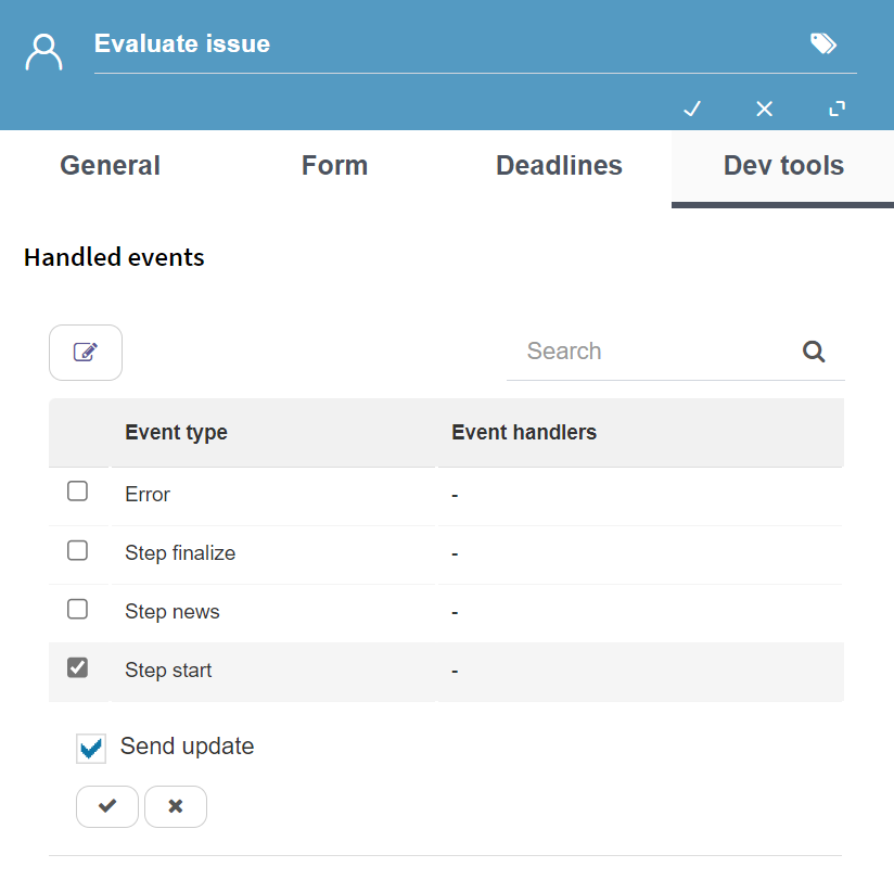
Fig. 575 Associate a handler to a task
Associate a handler to a flow event
To associate an event handler to a flow event, right click the template that contains the flows where the handler will be used and select “Event handlers”. This shows a list with the flow events. Check the event you want to associate the handler to, then click the edit button, or double click the corresponding row. A list of handlers appears, check the desired handler and click the button with the ✓ symbol.
The flow events are the following:
Thread status change: it occurs when a thread changes its status. For example, if a thread was waiting for someone to execute a task and that person responds to the task, the thread goes from Waiting to Executing.
Flow status change: it occurs when the flow changes its status. For example, if the flow arrives at a task step, there is a status change, given that the flow enters a state in which it is waiting for that task’s end or cancellation.
Thread error: it occurs when an error takes place during a thread’s execution.
Stage on time: it occurs when the flow’s current stage exceeds the time defined as the expected time. For more information on stages check the Stages section.
Stage out of time: it occurs when the flow’s current stage exceeds the defined maximum time.
Flow finalize: it occurrs when the flow ends.
Thread finalize: it occurs when a thread ends.
Thread wait: it occurs when a thread ends and waits for its sibling threads’ end.
Flow start: it occurs when the flow starts.
Thread start: it occurs when a thread starts its execution.
Thread fork: it occurs when a thread is divided into several threads. This occurs when a thread reaches a divergent parallel gateway or a divergent inclusive gateway that starts several threads.
Thread join: it occurs when two or more threads are joined. This occurs when the flow reaches a convergent parallel gateway or a convergent inclusive gateway that joins several threads.
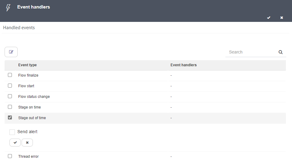
Fig. 576 Assign a handler to a flow event (in this case, the “Send alert” handler is assigned to the “Stage out of time” event).
Validations
Validations are small programs that are defined to execute operations in flow forms. To develop validations it is necessary to have knowledge of client-side scripting (Javascript). There are two types of validations:
The ones that are executed when Qflow loads a form on the screen. These validations allow you to modify the form data status before the user can modify it. To do this, the formLoad() method can be implemented.
The ones that are executed when the user clicks the form’s answer button (the button that starts the process in the case of start forms; the button that responds to the task in the case of response forms; the “Save” button in a flow edit form). These validations can be used to verify the data and emit an alert when it is not valid, thus preventing the user from making mistakes that hinder the form’s correct functioning. To do this, the formSubmit() method can be implemented.
Like custom forms, validations are defined in a package, process template or version and then associated to the forms in which you wish to use them. A validation can be used in various forms of many different flows. A validation can be associated to a form of any type (start form, user task response form, flow form and flow edit form).
Validation properties
A validation’s properties form has the following properties that can be modified:
Name
Description
Under the description there is a text area to write the validation’s code.
In previous Qflow versions, the validation’s programming language could be selected, with JavaScript and VBScript as options. However, VBScript is considered obsolete. For this reason, the posibility of selecting the language is only shown if the existing code is already of VBScript type. Otherwise, the shown language will be JavaScript, without the possibility of changing it.
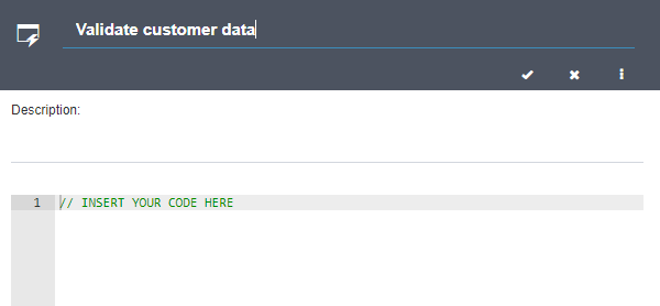
Fig. 577 Validation properties
Associating a validation to a form
To associate a validation to a process design element, double click the element to open its properties form (the element can be a start event, to associate the validation to a start form, a user task or a user notification task). In the “Dev tools” tab, check the validations you wish to associate to the selected element.
To associate a validation to the flow form or the flow edit form, open the form properties, by right-clicking the template and selecting “Flow forms”, “Flow form” or “Flow edit form”. This opens the selected form’s properties window. In the “Validations” section, check the validations you wish to associate to the selected element.
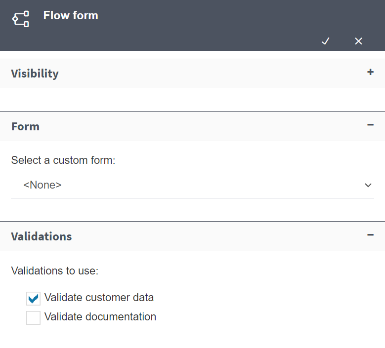
Fig. 578 Selecting a form’s validations
Bots
A bot is a computer program that performs tasks that are assigned to it by flows, with which it communicates asynchronously. Generally, tasks that are processed by bots are tasks that use a large amount of the hardware’s resources (memory, CPU) and thus must be performed by a process separate from the processes that Qflow’s services execute. A bot can even work in a different server from the one that hosts Qflow’s services. Bots are not meant for easy tasks that are executed in a few seconds and can be run in service or script tasks.
An interaction between a flow and a bot happens in the following manner:
A flow creates a task for the bot via an async service task. The task creation consists of storing the task’s information in a queue. That information includes the task’s parameters and indications of which bot must execute it. These indications are what is defined in Qflow Design.
The bot checks if it has pending tasks and when it does, it finds the new task and attempts to process it. The bot is a service or at least a process that periodically checks if it has new tasks in the queue. To that end, it uses the WebBot web service, which provides methods for accessing the queue and obtaining the pending tasks’ data to process them. It also provides methods for aborting a task or indicating that the task has been completed. Since the functionality to obtain tasks and update them is provided by a web service, the bot can be in a different server from the one with Qflow’s services.
Bot properties
A bot’s properties form has the following sections:
General: it allows you to enter a description and, in the “Executable by” property, the name of the user whose credentials will be used to execute the bot and invoke the WebBot web service.
Parameters: it allows you to define the bot’s parameters. The bot’s parameters are defined in the same way as an integration’s parameters. Check Integrations for instructions.
Notification:
Do not notify: if you select this option, Qflow will not notify the bot when it assigns it a new job. The bot will have to periodically consult the WebBot web service to discover if it has pending jobs.
Notify to message queue: in this case, Qflow will notify the bot that it has a new pending job through a message queue. The bot, in this case, must not periodically consult the WebBot web service, but rather suscribe to an MSMQ message queue and implement a handler for the event that will be triggered when there is a new job. If you select this option, you must specify the path of the message queue that will be used.
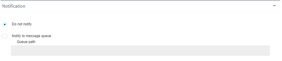
Fig. 579 Bot Notification section
Time out: it allows you to define a time limit for the bot to process the job. Once the limit has been reached, if the bot has not finished processing the job, the flow will continue its execution through the timeout connector of the async service task in which the job was assigned to the bot. If the async service task does not define a follow-up step through the timeout connector, it will be left in an error state. Check the Deadlines configuration section for instructions on how to define timeouts.
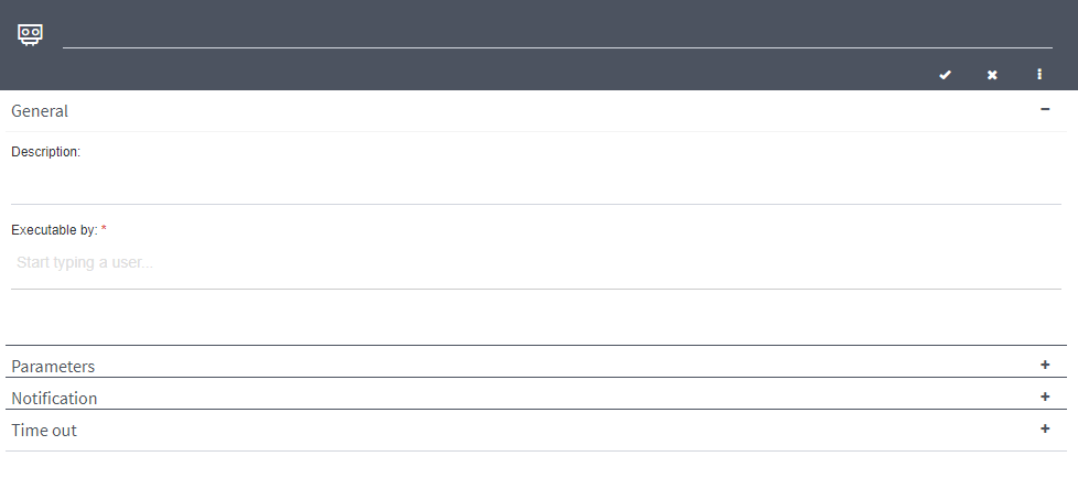
Fig. 580 Bot properties
Process design elements
This section gives a detailed description of the properties of each of the elements that can be part of a design. The first sections are about aspects that are common to several steps. For example, both a user task and a notification task require you to select one or more addressees.
General properties
There are properties that are common to all elements that can be added to a process design: the element’s name and its description.
The name always appears in an element’s properties form’s upper section, next to the Save, Cancel and Expand/Contract form buttons. The description appears in the “Documentation” section of the properties form.
Deadlines configuration
Certain design elements, such as user tasks or timer events, allow deadlines to be configured. Tasks allow the management of deadlines through actions like alerts, reminders, and delegations to minimize delays, while timer events pause the process until the deadline is reached. The forms for these elements include a section with the following properties:
Time information: in this property the timeout is specified, which can be defined in four ways:
Fixed date: it allows you to specify a date.
Variable date: it allows you to use the value of an application datum of Date or DateTime type. Qflow will execute the action in the date indicated by the value of the application datum. To be able to select this option, you must have a Date or DateTime type datum defined.
Fixed time: it allows you to indicate a time interval in seconds, minutes, hours or days. Qflow will execute the action once that interval has passed, from the moment the flow was started. Non-working days and hours do not count when doing this calculation, unless a calendar is used.
Variable time: this option is similar to the previous one, but it allows you to use the value of an application datum of Number type to indicate the interval’s value. This value can be interpreted as being expressed in seconds, minutes, hours or days. To be able to select this option, you must have a Number type datum defined. Non-working days and hours do not count when doing this calculation, unless a calendar is used.
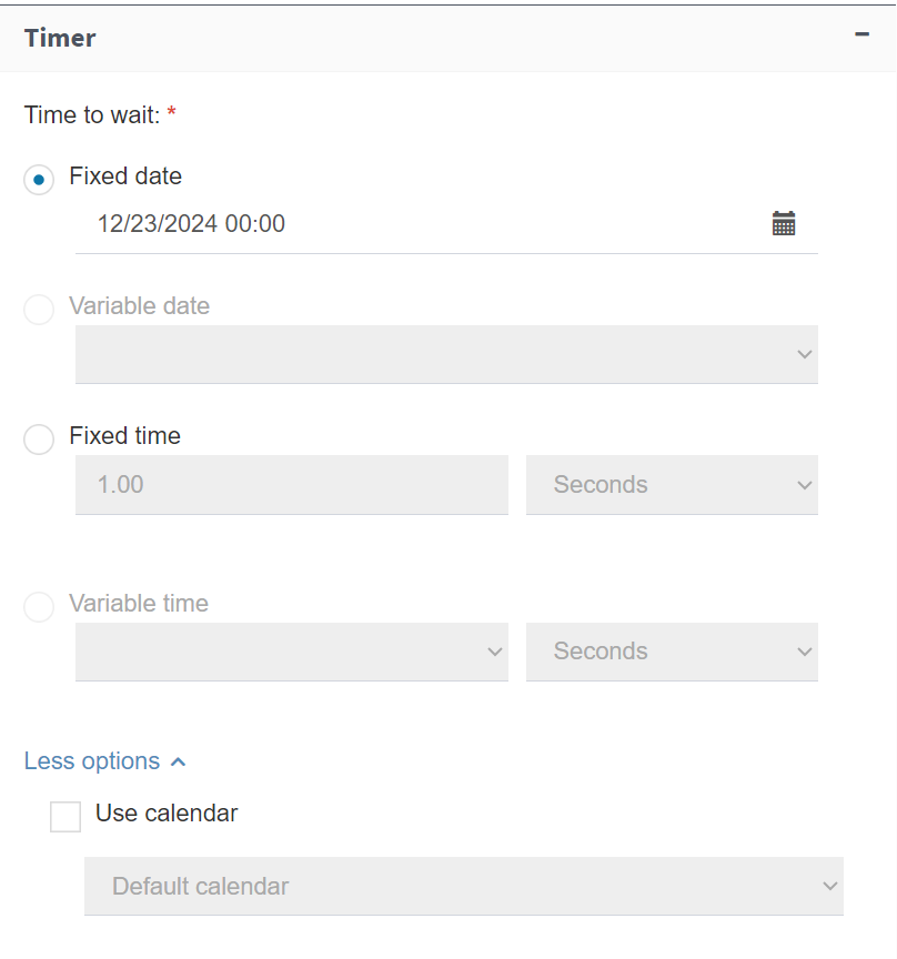
Fig. 581 Deadlines
Data, roles, attachments and comments visibility
Qflow allows you to configure which data, roles and attachments users can see or modify during a flow and where they can do so. Comments can also be managed, allowing you to add them or view existing ones.
Users interact with flows through forms:
Flow start form: it is the form that appears when you start the flow and is related to the start event.
Flow response forms: they are the forms that users use to respond to flow tasks. They are associated to user tasks.
Flow form: it is the form that appears when someone clicks a flow to examine its information. It is associated to the flow and does not allow you to modify the data.
Flow edit form: it is a form similar to the flow form, but which allows you to modify data.
To define the level of access to the flow information, it must be defined for each of these forms and in the case of response forms, for each user task. It is not necessary to define the information access in those forms where you do not wish for data, roles, attachments or comments to be available, since by default, these are not present in the response form.
The flow start form is associated to the start event, since it appears when the flow is started. To modify the information access level during the flow’s start, open the start event’s properties form and look for the “Visibility” tab. There you can specify which data and roles are present and shown in the form, and which can be modified by the user. The attachment and comment visibility options are also there. These options are explained in detail later.
The case of response forms is similar. Qflow’s response forms are associated to user tasks, since they appear when a user wishes to respond to a task assigned to them. To modify a user task’s visibility, you should proceed in the same manner as with a start event.
To modify the level of access in a flow form, access the flow form’s properties window by right-clicking the version and selecting the “Flow forms”, “Flow form” option. That window has a “Visibility” section. Do the same to modify the visibility in the flow edit form, but selecting “Flow forms”, “Flow edit form”.
Data and roles visibility
Data and roles visibility are configured in the same way. This section explains how to configure data visibility, but the same instructions apply for roles. Application data visibility is modified through a table (Fig. 582) that shows the application data list. If there are two data with the same name and a different visibility than “Missing”, an error will be shown when saving.
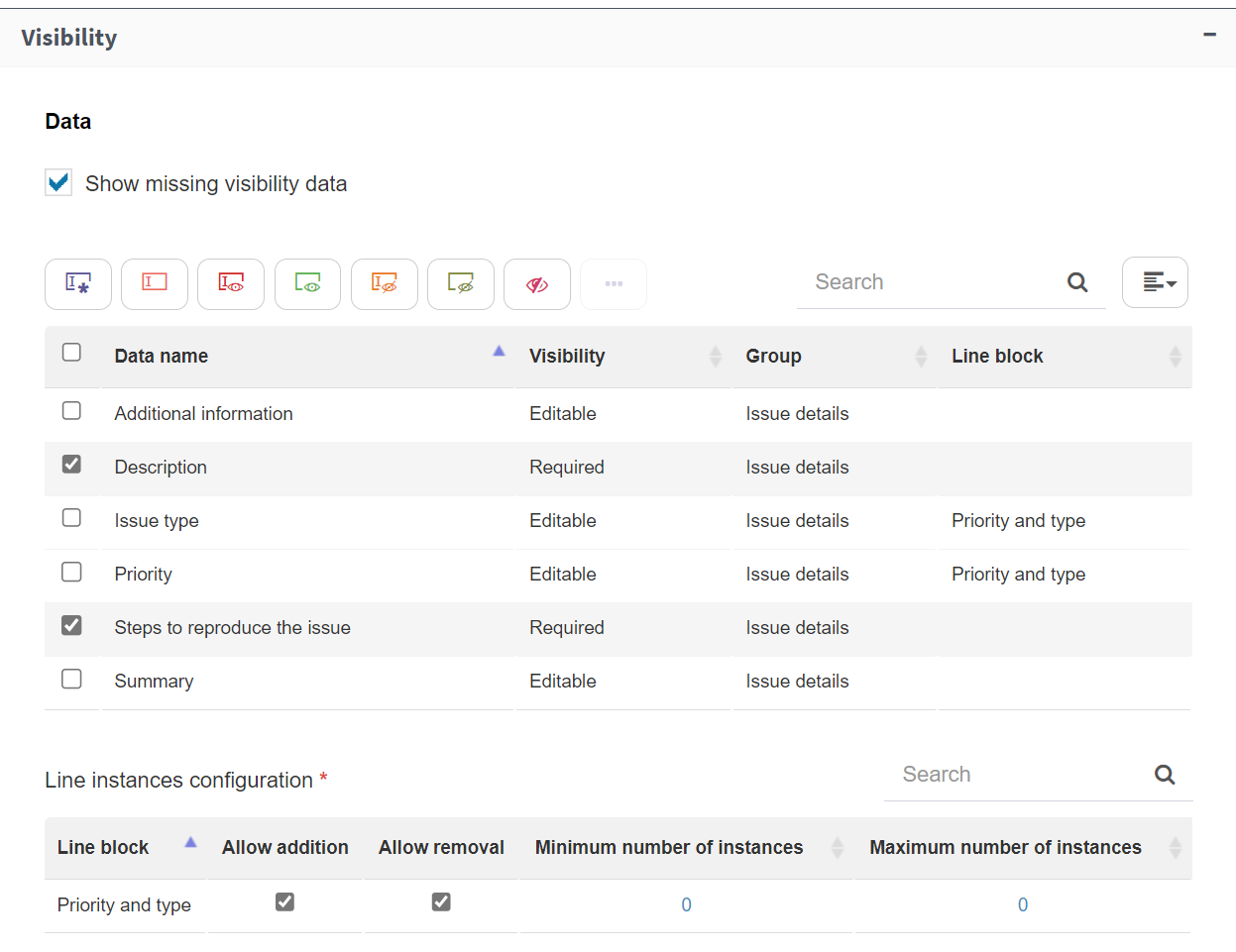
Fig. 582 Data visibility
To modify a datum’s visibility, select it and click on the button that appears above the table, it will show the available visibility options. (Fig. 583 shows which button corresponds to which visibilidad; to see it in the site’s own screen, place the mouse cursor over the button). Several pieces of data can be selected simultaneously. The options are:
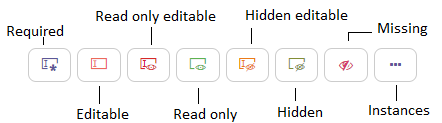
Fig. 583 Visibility buttons with their meanings
Required: the user can see and modify the data value, and also, if the data does not have a value, they are required to enter one.
Editable: the user can see and modify the data value.
Read only: the user can see the data value, but cannot modify it.
Missing: the data is not in the form. It is as though it did not exist.
In turn, if you want to be able to modify a data entry that is set to read-only or absent via a script on the page, you must check the option in the ‘Code/Dep.’ table (Fig. 585), which can be viewed using the button at the top right of the table (Fig. 584).

Fig. 584 Column display option ‘Code/Dep.’
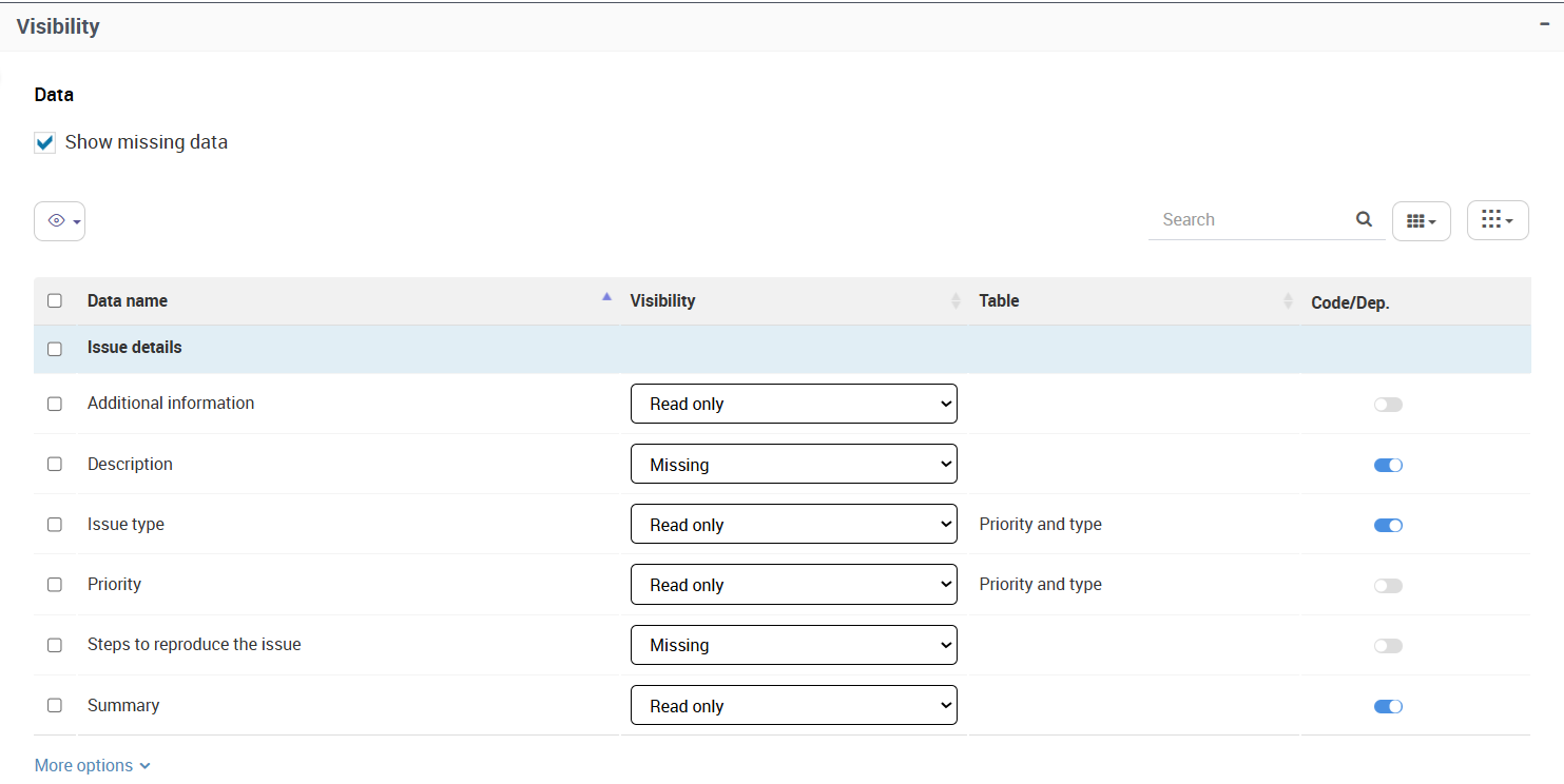
Fig. 585 Data table with ‘Code/Dep.’ column
If a datum belongs to a table, the visibility properties that are edited will apply to the entire table. Therefore, these properties can also be modified through a grid (Fig. 586) that appears in the ‘More options’ section below the data table. This grid apears when at least one of the pieces of data belonging to the table has a visibility that allows its modification (required, editable or has the column option checked). The existing columns that allow modifying the visibility properties specific to that data are:
Allow addition: it specifies whether adding new instances to the datum or new lines to the line block (if the datum belongs to one) is allowed.
Allow removal: it specifies whether removing data instances or lines from the block (if the datum in question belongs to one) is allowed.
Maximum number of instances: it specifies the maximum number of instances that a datum can have or the maximum number of block lines if the datum belongs to a line block. If the datum has that number of instances, no more can be added, even if addition is permitted.
Minimum number of instances: it specifies the minimum number of instances that a datum can have or the minimum number of block lines if the datum belongs to a line block. If the datum has that number of instances, no more can be removed, even if removal is permitted.

Fig. 586 Additional visibility options table for data that accepts multiple values
Group ordering
In those elements that use a form (start event, user tasks and flow forms configuration), data visibility has an additional possibility, which is group ordering. Under the instances section you will find a slider that, when checked, will show you the groups corresponding to the data that has a visibility that makes it appear in the form (editable, required, or read only).
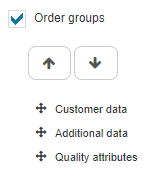
Fig. 587 Group ordering
You can select the group you wish to move and then click the arrows to move it up or down. You can also drag the groups to order them. This group order will be reflected in the form. Data that does not have a group will remain inside the “Application data” group, which cannot be ordered.
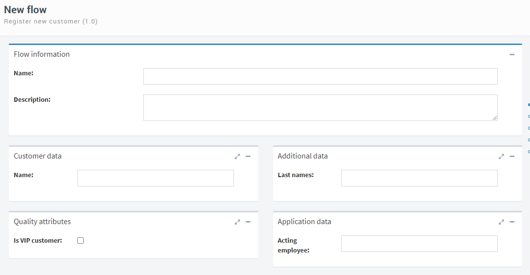
Fig. 588 Ordered groups
Attachment visibility
Attachment visibility options are the following:
Accessibility: this property indicates the level of access that users will have to attachments. The possible options are:
None: Qflow does not show attachments in the form.
List only: Qflow shows attachments, but does not allow you to open them or modify them.
Read only: Qflow shows attachments and allows you to open them.
Editor: Qflow shows attachments, allows you to open them and modify them.
Total: Qflow shows attachments, allows you to open them, modify them and remove them.
Allow addition: if this option is checked, users will be able to add attachments to the form.
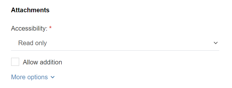
Fig. 589 Attachment visibility
It is possible to make advanced configurations by expanding the “More options” section, where the following parameters can be adjusted:
Limits:
Maximum number of attachments: it indicates the maximum number of attachments that the step can have. Qflow will not allow you to add attachments over this value, unless it is 0, which means there is no maximum.
Minimum number of attachments: it indicates the minimum number of attachments that the step can have. Qflow will not allow you to remove attachments if doing so implies that the attachments number becomes less than this value.
Maximum size of an attachment (KB): it allows you to specify the maximum size in kilobytes that attachments can have (the default option, 0, means there is no limit). If you specify a value, Qflow will not allow you to attach files with a size greater than the one specified.
Show only: it makes Qflow show only the files that match one of the regular expressions entered in this property. (*)
Edit only: it makes Qflow allow the modification of only the files that match one of the regular expressions entered in this property. (*)
Add only: it makes Qflow allow you to add only the files that match one of the regular expressions entered in this property. (*)
Delete only: it makes Qflow allow you to delete only the files that match one of the regular expressions entered in this property. (*)
(*) See Regular expressions of attachment filters, for more information.
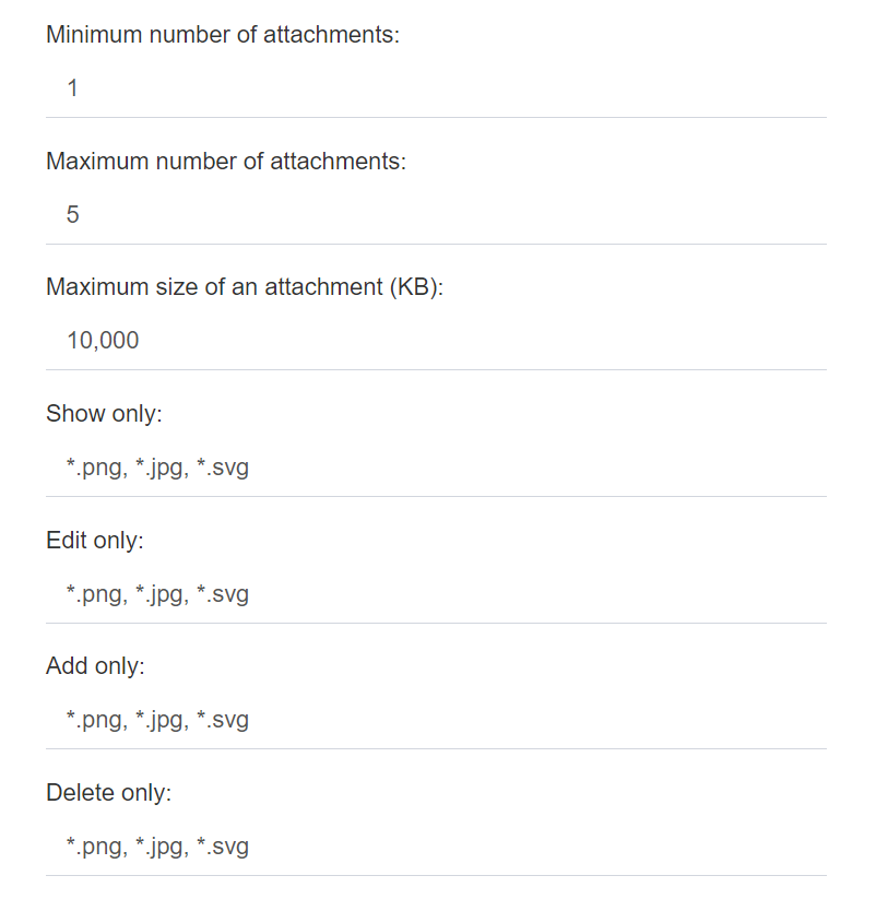
Fig. 590 Attachment visibility (more options)
Regular expressions in attachment filters
Attachment filters are used specifically via regular expressions similar to the ones that Windows uses for its file system, in which an asterisk (“*”) substitutes any number of characters. For example, the expression “*.zip” means “every file with .zip extension”.
A filter can use several expressions separated by “;” or by “|”. For example, if the “Read only” filter has the expression “*.zip;*.rar;License.pdf”, Qflow will only show files with “zip” and “rar” extensions, as well as the file named “License.pdf”.
Character “?” substitutes an occurrence of any character. Some examples: expression “*.???” represents any file with a three-character extension; expression “document?.doc” represents any file whose name starts with “document” and has an additional character before the extension (“document1.doc”, for instance, but not “document12.doc” or “document.doc”).
Character “!” allows you to negate an expression. It can only be used at the start of the filter. For example, if in the “Show only” filter the expression “!*.exe;*.bat” is written, Qflow will only show files that do not have “bat” or “exe” extensions.
Comment visibility
Qflow forms have the option of adding comments when filling them (in the case of those that are not of read only type) and seeing the existing comments. This allows users to give and obtain extra information about the flow that is considered important but is not part of its data. The visibility options for these comments are the following:
Allow addition: the user can add a comment to the flow if they wish.
Required: the user is obliged to add a comment; if they do not, they will not be able to complete the form. This option can only be selected if you have already selected “Allow addition”.
Ver historial de comentarios: el usuario puede visualizar el historial de comentarios del proceso.
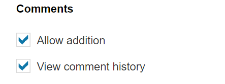
Fig. 591 Comment visibility
If viewing and adding comments is allowed, when you respond to a task, for example, you see the form as in Fig. 592.
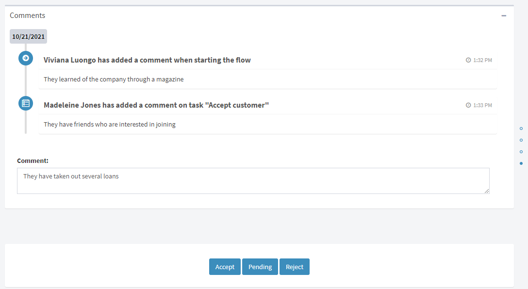
Fig. 592 Form with comments
The comments congifuration differs for user tasks, in which we have the ability to choose whether comments are required depending on the response chosen by the user, as well as the option to add said response to the comment log. For more information, see the User task section.
Tags
Many properties of Qflow’s steps allow you to use tags. This means that the values of these properties do not have to be determined during a process’ design, but Qflow can obtain them from where it is indicated when it needs to use them. For example, it is common to include the value of some application datum (like a customer’s ID number or their name) in user task’s subjects. In this case, instead of the task saying something like “Process the customer’s request”, it can say something like “Process the request of customer John Smith, ID 111111”.
Properties for which tags can be used have an icon with a tag next to it (Fig. 593). If you click this icon, a list appears with the items that can be selected for the tag. If, when you see this list, you type, the list will limit itself to the elements that contain the text you entered. You can also choose to only show items of a specific type in the list (for example, only application data). To do that, click the corresponding icon in the list’s lower section (Fig. 593, where it says “Data”, “Roles”, etc).
You can also enter a tag without clicking the tag icon, by simply entering the “#” symbol in the property: this will also make the list of items that can be used for the tag appear.
The item types that can be used in tags are:
Application data: the data value is used.
Process template roles: the name of the user who performs the role is used.
Text type application parameters: the parameter value is used.
Flow information: for example, the flow name or its start date.
Others: for example, the current date.
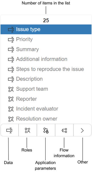
Fig. 593 Tags
Step types
In general, steps are divided into three types: events, activities and gateways. An event represents something that happens in the step and there are three types: start, intermediate and end. An activity represents a work unit to do in the flow and it can be a task, an automatic process or a subprocess.
Start events

Fig. 594 Start event
The start event marks the beginning of a flow and defines the point at which a user starts it. For example, to use a custom form as a start form, it is associated with the start event. When the flow is started, its execution begins at this event, which must be unique.
The properties form of a start event has the following tabs:
General
Flow names and descriptions can be specified beforehand, using tags, so that the user does not have to enter them when starting the flow.
Auto-generated name: a text with tags to indicate how the flow’s names must be formed.
Auto-generated description: a text with tags to indicate how the flows’ descriptions must be formed.
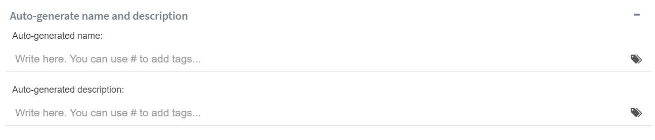
Fig. 595 Autogenerated process name and description section
We can also share a link with people outside the organization so they can start this flow without needing a user in the system.
Allow people outside the organization to start flows with this template version: if this option is checked, this process will be able to be started by people outside of the organization. When this option is checked, the rest of the options of the feature are shown.
Public link: it shows and allows copying the link that must be shared with external users to star the process.
Embedded code: it shows and allows copying a segment of HTML code used for embedding this process’ start form on any web site.
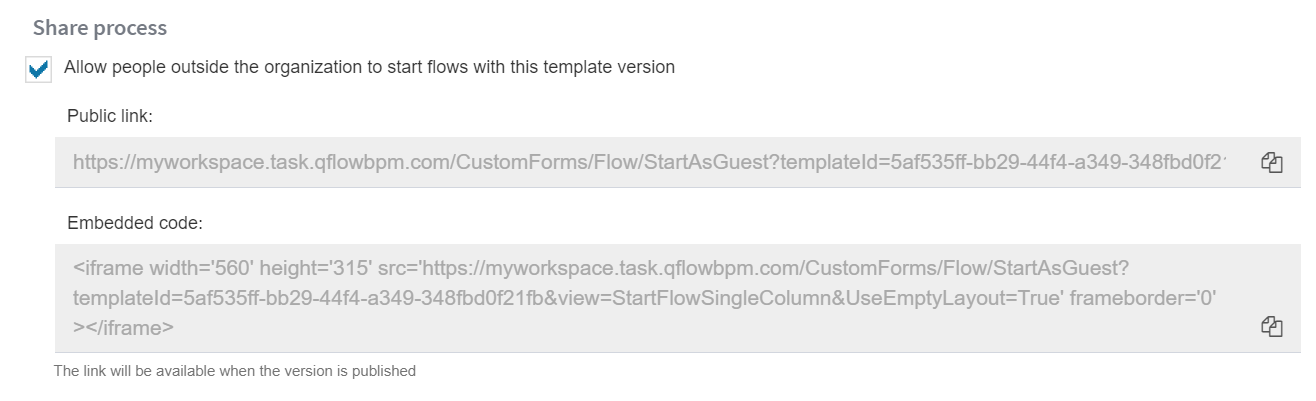
Fig. 596 Process start for external or anonymous users configuration
Within the advanced options, it is possible to configure a confirmation message that will be visible to users, both external and from the system, when starting the flow. This message can be customized using tags to incorporate dynamic data. Additionally, you can define the stage that will start when executing this step and set the flow flag.

Fig. 597 Confirmation message to user
Form
For information on how to configure the visibility, check Data, roles, attachments and comments visibility.
Dev tools
In this tab, you can choose validations, from the existing ones, to run in the start form (see Associating a validation to a form).
End events
The end events that Qflow implements are the Simple end event, which we will call End event (Fig. 598), and the Terminate end event (Fig. 599).

Fig. 598 End event
Fig. 599 Terminate end event
End and terminate end events finish flow executions. A terminate end event finishes the flow’s execution even if some threads are still executing. In that case, Qflow finishes those threads and the flow ends its execution. An end event, on the other hand, waits for all threads to finish and once they have, it ends the flow.
The properties form of these events allows you to configure both the flow progress and its flag.
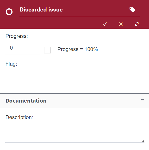
Fig. 600 End event properties
User task
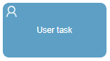
Fig. 601 User task
A user task assigns a task to a user or group of users, and the addressees are defined through process template roles. When a user accesses a task’s form in Qflow Task, they must select an option from a list to update the task’s status.
General
Message subject: the subject text of the message that will be sent or shown to the addressees. If the task is configured to send notifications, it is used in the subject of the e-mail message that is sent to the addressees. It can be specified through a tag (see Tags).
Addressees: list of the task’s addressees. The addressees are template roles. To specify an addressee, start typing their name and select it when it appears as an option. Additionally, in this section we can configure if the task can be responded by external users or not. For more information, see External task response.
Expanding the “More options” section allows you to configure:
Sends notifications: it allows you to define if you wish for the step to send notifications via e-mail to its addressees. If the option is unchecked, Qflow will not send e-mail messages to notify the task’s addressees that they have a pending task.
Task manager: it allows you to specify a role who will be the task manager. The manager can respond in place of any of the addressees. They can also delegate the task and send alerts.
Alternative addressee: it allows you to specify a role so that, if the task’s original addressee cannot complete it, it is possible to select that role’s members as addressees when delegating it.
Responses: a table that contains the responses that will be available for whoever performs the tasks. The buttons allow you to add or remove responses, as well as reorder them through the arrows. Each response has the following properties, which are modified in the table where they are shown:
Text: the response text. It is what is shown to the user. When a response is added, the text has a default text. To modify it, click that text.
Key: a text that identifies the response, but that is not shown to the user. The key is used to evaluate conditions that use it. The key is modified in the same way as the text, by clicking it.
Comment required: if set to “Yes”, it indicates that the response of the task must have comment.
Type: it indicates the response type, which can be not final, final or terminal final. When a user selects a final response, they finish their task and cannot continue working on it. When they select a response that is not final, the changes they made in the data are saved, but their task is still pending. Since a task can be assigned to several addressees, the fact that an addressee has selected a final response does not necessarily mean that the flow will continue its execution, because other addressees may not have finished their parts of the task. In this case, multiple response criteria (see below) define under which conditions the the flow will consider the task finished and continue its execution. This does not apply when the user selects a terminal final response; in this case, the task will finish even if the other addressees have not answered yet, regardless of the multiple response criteria.
Allow quick response: if this option is checked, it allows this task to be responded from the “My tasks” view in Qflow Task, as well as responding it together with other tasks that share the same responses and allows response from the task notification email. This option is available only to those tasks that do not have any required elements in their visibility (application data, roles or attachments). For more information about the use of the functionality, see the Task manual.
Add Reply to Comments: allows responses to be added to Qflow Task’s comment log.
Expanding the “More options” section allows you to configure:
User confirmation message: it allows writing a message that will be displayed to users (both system and external) when responding to the task. It can be decorated with tags within its content.
Multiple response criteria: it allows you to specify when the flow must continue, when it has more than one addressee. Options are:
Some user has answered: when a user selects a final response, the flow will finish the task and continue its execution.
All the users have answered: the flow will continue its execution only when all addressees have selected a final response.
At least “X” users have answered: when a number (X) of users have responded, the flow will continue its execution. If this option is selected, the “Quantity/Percentage” field is enabled for you to specify the quantity (X).
At least “X” percentage of the users have answered: similar to the previous option, but a user percentage is indicated instead of an absolute quantity.
Response display mode: it allows you to configure how the task responses are shown in a standard form in Qflow Task.
Form
Allows you to specify access to data, roles and attachments (see Data, roles, attachments and comments visibility).
Deadlines
Deadlines are used to prevent or mitigate delays in tasks through alerts, reminders, delegations and timeouts. Alerts and reminders are notifications that are sent when a time limit expires. Delegations consist of reassigning tasks and timeouts allow the flow to take a path different from the one it would have taken if a time limit had not expired.
The deadlines tab shows a table with the deadlines that have been defined. It has three buttons to add, modify and delete time controls (Fig. 602).
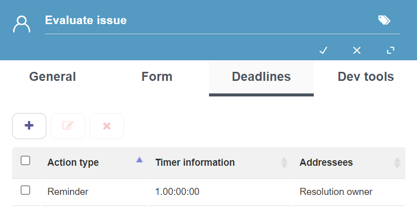
Fig. 602 Deadlines
When you edit a deadline, a form is shown like the one in Fig. 603.
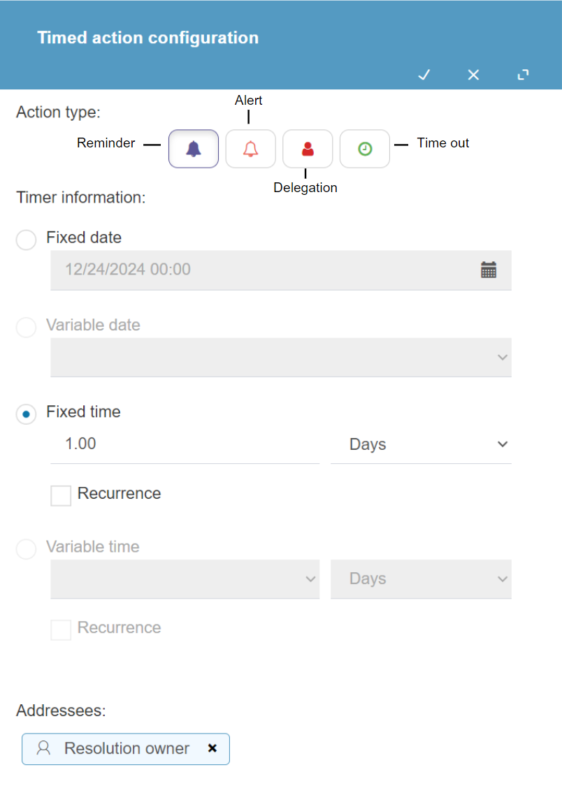
Fig. 603 Deadlines
This form has the following properties:
Action type: several buttons are shown. Each one corresponds to an action class. A class is selected by clicking it. Possible classes are:
Reminder: Qflow sends a notification with a reminder for the selected addressee.
Alert: Qflow sends a notification with an alert for the selected addressee.
Delegation: Qflow reassigns the task, giving it to the selected addressee.
Time out: Qflow interrupts the wait, abandoning the step’s execution and continuing with the flow execution through the timer boundary event. For more details on how to add boundary events see Add boundary event.
Timer information: these properties define the time limit for the time out that the action specified above will trigger. For instructions, check Deadlines configuration.
Addressees: select the action’s addressees here. For alerts and reminders, addressees are those who will receive the notifications. For delegations, they are who the task will be reassigned to. Time outs do not have addressees. To add an addressee, start typing the name of a role that is available in the template you are using and when you see it in the list that appears, select it.
Dev tools
Allows you to configure event handlers (see Associating a handler to a task event) and validations (see Associating a validation to a form).
External task response
User tasks can be configured to be responded by users external to Qflow, which is indicated in the “Participants” section in the task’s configuration panel.
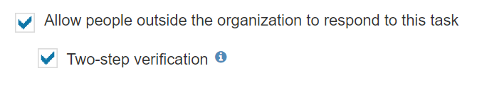
Fig. 604 External task response configuration
If this option is checked, the task will allow you to include addressees that are not template roles, in the form of e-mail addresses.
When the task is executed, an e-mail with a link will be dispatched to the addresses marked as addressees of the task, which allows them to access to the task’s response form. Those who have the link can enter this form without the need of a Qflow user account. The link and form will be valid as long as the task is still available.
In this section, it is also possible to configure if the task requires two-step verification. By enabling this option, external users must enter a verification code when accessing the task’s form. This code can be requested directly from the form and will be sent to the e-mail address used to access it. This ensures that the user who responds to the task is the same one who received the link.
We can add external addressees in the form of text application data and parameters, or by directly writing e-mail addresses on the “Addressees” field of the task.
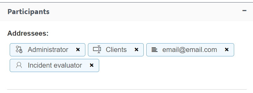
Fig. 605 Roles, data, parameters and e-mail addresses as task addressees
Keep in mind that marking this option does not prevent using roles as addressees, which means that it is possible to have a single task that dispatches to system users as well as external users. The history logs will reflect the actions of external users identifying them by the e-mail address to which the link was sent.
If the task has a role defined as “Task manager”, it will have permissions on the tasks dispatched to external addressees.
User notification task
Fig. 606 User notification task
A user notification task sends a notification to Qflow’s users. Users usually receive notifications by e-mail, but they can also see them in Qflow Task. In that regard, a user notification task is similar to a user task. The difference is that it does not require any actions from its addressee, but simply lets them access a form that shows them the information. This form can be, like in the case of other steps that use forms, a custom one.
A user notification task’s properties form has the following tabs:
General: allows you to specify the e-mail subject that the addressees configured in the “Participants” section will receive.
Form: it allows you to define which application data, roles, attachments and comments will be visible in the form. (see Data, roles, attachments and comments visibility). It also allows you to add a help text for the users. When they see the notification in Qflow Task, they will be able to see the help text by clicking the help icon (“?”). The text can contain HTML code.
Dev tools: it allows you to associate validations to the task. See Associating a validation to a form.
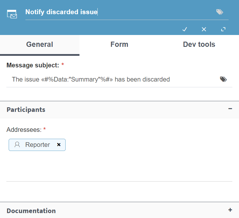
Fig. 607 User notification task basic configuration
Mail task
Fig. 608 Mail task
A mail task sends an e-mail message to the addresses specified in its properties. A mail task uses the SMTP service configuration to send its messages.
A mail task’s properties form has the following sections:
Addressees: allows you to configure the task’s addressees.
Content: it allows you to specify the text of the message that will be sent, as well as said message’s format and which flow attachments will be sent as attachments to the message.
Addressees
The “Addressees” section shows a space to write the e-mail addresses of the message’s addressees. You can write several addresses or enter application data or system parameters of type text, which contain e-mail addresses.
Content
The “Content” section has the following properties:
Subject: the message subject’s text. A tag can be used (see Tags).
Body: the message’s main text. A tag can be used (see Tags).
Programming language: it indicates whether the message body is specified in HTML or plain text.
HTML: the message body is specified in HTML.
Text: the message body is specified in plain text, without HTML tags.
In the lower half the message is written. You can use tags to take, for example, values from an application datum. To do this, write “#”.
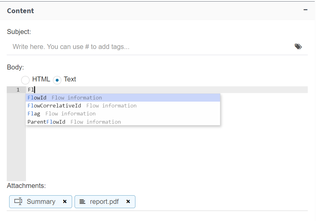
Fig. 609 Message content properties
Formula task
Fig. 610 Formula task
A formula task takes application data or process roles, performs operations on them and generates a result that is also accordingly stored in an application datum or role.
This task’s execution will perform the operations in the specified order. You can use a value that is pre-calculated and stored in some application datum or role in a later operation.
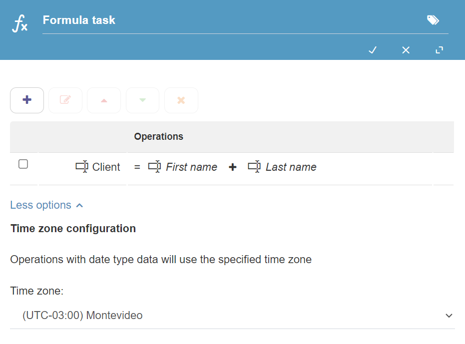
Fig. 611 Formula task properties
When expanding the “More options” section, you can select a time zone for all the dates that are handled in the step. Dates in Qflow have a time zone that influences the calculations performed on them. Since a flow with dates can be executed in a different time zone from the user’s (if the server is somewhere else), to avoid ambiguities, you can specifically indicate which zone the dates are considered to be in. In the case that you import a formula task from a previous Qflow version, the “Server time zone” option will be automatically selected.
Operations
The configuration form of a formula task shows an initially empty table with the formula definition, which is composed of operations (each table row corresponds to an operation). To add a new operation to the formula, click the “+” button. This opens the new operation’s form, to the right of the formula table (Fig. 612).
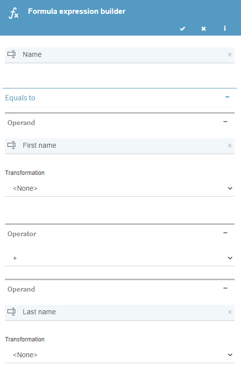
Fig. 612 Expression definition
An operation’s properties are the following (Fig. 612):
Target: it is the first property. Where it says “Start typing…”, start writing the name of the application datum or role in which you wish to store the formula’s result.
First operand: after where it says “Equals to”, you can enter the first operand, by writing where it says “Start typing…”. The operand can be:
Value: a fixed value. In this case, write the value.
Application data: an application datum of any type. If you start typing the name of an application datum, it will soon appear in a list that is displayed while you write.
Function: the result of a function. For now, the only available function is GetDate(), which returns the current date according to the time zone specified in the task. This function can be selected if you start typing “GetDate()”.
Role: a process template role. It is selected in a similar manner to an application datum.
The first operand depends on the target: if the target is a role, the operand must also be one. If the target is a datum, the value that the first operand can take depends on the target’s data type.
Transformation: this option allows you to apply a transformation to the operand before operating with it. The possible transformations depend on the operand’s data type.
Number data: in general, these transformations only make sense if the operand is a datum that allows multiple values.
Average: it calculates the values’ average.
Count: it counts the number of values.
Max: it takes the maximum of the values.
Min: it takes the minimum of the values.
Sum: it takes the sum of the values.
Text data:
Left: it takes only the operand’s first characters. The number of characters to take is specified in the “Length” property.
Left Trim: it cuts all the blank spaces that may exist at the operand’s beginning.
Mid: it only takes the operand’s middle characters. The position from which the characters must be taken is indicated in the “Start” property (0 corresponds to the first position). The number of characters to take from that position on is specified in the “Length” property. For example, if the operand’s value is “Hello World!”, Start = 6 and Length = 6, the transformation’s result will be “World”. For the same operand, if Start = 0 and Length = 5, the result will be “Hello”.
Right: it takes only the operand’s last characters. The number of characters to take is specified in the “Length” property.
Right Trim: it cuts all the blank spaces that may exist at the operand’s end.
Trim: it cuts all the blank spaces that may exist both at the operand’s beginning and end.
Date: the values returned in these transformations are calculated according to the time zone specified in the task.
GetDay: it takes only the day.
GetHour: it takes only the hour.
GetMinutes: it takes only the minutes.
GetMonth: it takes only the month.
GetSeconds: it takes only the seconds.
GetYear: it takes only the year.
Operator: the operation’s operator. It is possible to not select any operator and only apply a transformation to the first operand, without performing any operations.
+ (sum): in the case of roles, it works as a set union (the result of adding two roles is a set with both roles’ members).
- (substraction): in the case of roles, it works as a set substraction: the result are all the members of the first role that are not in the second role.
* (multiplication)
/ (division)
mod (remainder of dividing the first operand by the second)
AddDay: it adds the number of days indicated by the second operand to the first date-type operand. The second operand must be a number.
AddHour: it adds the number of hours indicated by the second operand to the first date-type operand. The second operand must be a number.
AddMinutes: it adds the number of minutes indicated by the second operand to the first date-type operand. The second operand must be a number.
AddMonth: it adds the number of months indicated by the second operand to the first date-type operand. The second operand must be a number.
AddSeconds: it adds the number of seconds indicated by the second operand to the first date-type operand. The second operand must be a number.
AddYear: it adds the number of years indicated by the second operand to the first date-type operand. The second operand must be a number.
Second operand: select the second operand from the options. These options are the same as for the first operand. The second operand depends on all the previous elements: the target, the first operand with its possible transformation and the operator. For this reason, some data may not appear as an option for the second operand.
Gateways
Gateways allow you to modify a flow’s route, be it by creating several parallel paths in the process or by selecting a path of many possible ones that come after the gateway.
All gateways are connected to various elements through their connectors. What changes according to the gateway type is if, once a flow goes through it, it continues using all paths, some of them or just one.
Gateways can be of the following types:
Exclusive gateway: it selects one of various possible paths for the flow to continue its execution.
Inclusive gateway: it selects one or more of various possible paths for the flow to continue its execution, so it can generate several parallel threads.
Parallel gateway: it generates as many parallel paths as it has outbound connections.
Gateways are used in pairs: a gateway is used and, in the place where the paths that started with it end, another gateway is added. In the case of the exclusive gateway, this is not mandatory. In the case of gateways that generate parallel threads (the parallel and inclusive ones), the second gateway of the pair (convergent gateway) is mandatory and has properties that allow you to define under which conditions the flow will continue its execution when one of the paths finishes its execution.
Exclusive gateway

Fig. 613 Exclusive gateway
An exclusive gateway selects one of various possible paths for the flow to continue its execution. It defines a condition for each of its outbound connections. If some condition is true when the flow reaches the gateway, the flow will use that connection to continue its execution. If no condition is true, the flow will use the default connection to continue its execution (see Specifying the default connection for instructions on how to define the default connection). If more than one condition is true, the flow will use the first of the conditions to continue its execution. In no case is more than one connection used: an exclusive gateway does not generate parallel paths.
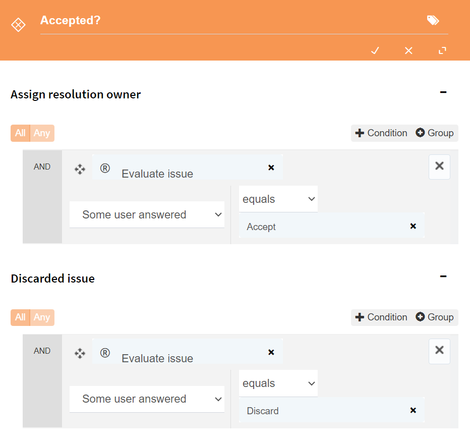
Fig. 614 Defining conditions in an exclusive gateway
Parallel gateway
Fig. 615 Parallel gateway
Parallel gateways are used in pairs: the first one (divergent parallel gateway) divides the flow in several threads. The flow reaches the parallel gateway and continues its execution by using all of the gateway’s outbound connections. The second gateway (convergent parallel gateway) joins the threads, making all the paths the flow had been divided in converge again into one.
The properties form of the gateway that performs the separation is very simple: it only allows you to enter a name and description.
The second gateway, which joins the threads, allows you to define the conditions under which the flow must continue its execution (for example, if it must wait for all threads to finish). It also specifies what to do with the pending threads if it does not wait for all of them. These options are detailed in Convergent gateways properties.
Inclusive gateway

Fig. 616 Inclusive gateway
An inclusive gateway is a sort of hybrid between an exclusive gateway and parallel gateway: it selects one or more of various possible paths for the flow to continue its execution, so it can generate various parallel threads. It defines a condition for each of the outbound connectors. Once the conditions have been evaluated, the flow continues its execution through all the connections whose conditions are met. If more than one condition is true, the gateway generates various parallel paths.
Like parallel gateways, inclusive gateways must be used in pairs. The second gateway of the two (the convergent gateway) has properties that allow you to define when the flow must continue its execution when it reaches the gateway and what it must do with any pending threads. These properties are in the convergent gateway’s “Advanced” section. This section’s options are described further down, in Convergent gateways properties.
The properties form of the first gateway (divergent gateway) is very simple and only allows you to enter a name and description.
Specifying the default connection
The default connection is the one that an exclusive gateway uses when none of the conditions it contains is evaluated as true. To define a default connection, select one of the gateway’s connections, right-click it and select, in the context menu, “Default connection” (Fig. 617).
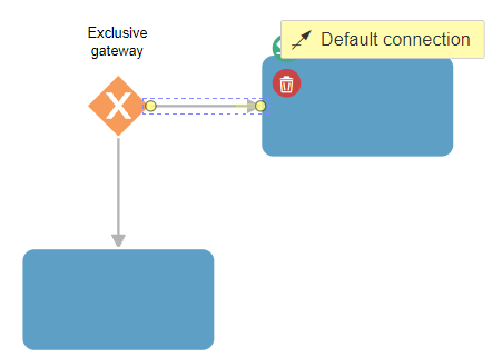
Fig. 617 Specifying a default connection
Finally the connection should look like Fig. 618 shows.
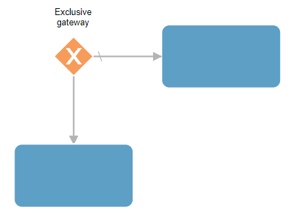
Fig. 618 Default connection
Conditions specification
Exclusive and inclusive gateways contain conditions in their properties that Qflow evaluates when it reaches one of them. These conditions determine through which path (in the case of the exclusive gateway) or paths (in the case of the inclusive gateway) the flow will continue its execution, once the gateway is left behind.
To define the conditions of a gateway, open the properties form. This form is divided into subsections, each representing a possible path that the gateway can take in the flow. In each subsection, it is possible to set a condition.
To define a simple condition, click the “+Condition” button. That makes Qflow add an element to the conditions list (Fig. 619).
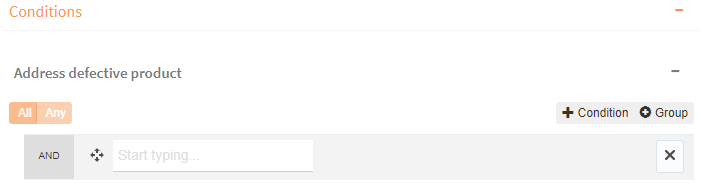
Fig. 619 New condition in conditions list
Once the condition has been added, its components must be specified. Where it says “Start typing…” you must type the name of the item that you wish to use in the condition. The item can be an application datum, a text application parameter, or a user task that was executed previously. Once the item has been selected, select the operator to use and finally the value with which you wish to compare it. If the selected item is a user task, you will be able to select the voting criterion, which allows you to specify how to evaluate the response if the task addressees are many:
Some user answered: if some addressee answered what is specified in the operator-value combination, the expression is true. Otherwise, it is false.
All users answered: if all of the task’s addressees answered what was specified in the operator-value combination, the expression is true. Otherwise, it is false.
None of users answered: if no addressee answered what was specified in the operator-value combination, the expression is true. Otherwise, it is false.
X answered: if X addressees answered what was specified in the operator-value combination, the expression is true. Otherwise, it is false. If this option is selected, a box is enabled to specify X’s value.
X% answered: if X% of the addressees answered what was specified in the operator-value combination, the expression is true. Otherwise, it is false. If this option is selected, a box is enabled to specify X’s value.
Most selected answer: if the most selected answer was the one specified in the operator-value combination, the expression is true. Otherwise, it is false.
The value can be a fixed value like “2”, but you can also type the name of an application datum or text parameter so the comparison is made with its value or the value of a user task’s response key or name. In this last case, the comparison will be made with the key of the response that was given to the previously answered user task. This allows you to build conditions such as “If the ‘Status’ application datum is equal to the response that was given to the ‘Approve’ user task.”
If you add another condition, you must decide if the second condition must be met simultaneously with the first, that is, if what is evaluated is “The first condition is met AND the second condition is met” or “The first condition is met OR the second condition is met”. That is what the “All” and “Any” buttons are for. If you click “All”, Qflow shows the text “AND” to the left of the conditions. If you click “Any”, it is enough for one of the conditions to be met and to the left of the conditions the text “OR” appears.
To be able to combine “AND” and “OR” you have to use condition groups. To add a group, click “+Group”. You can then add conditions inside the group. The group has its own “All” and “Any” buttons, to determine how the conditions are combined inside the group (all are combined with “AND” or all are combined with “OR”). At the same time, groups are combined in the same manner as conditions, with “AND” and “OR”. A group can contain groups: by combining groups of conditions joined with “AND” with groups of conditions joined with “OR”, you can build any complex condition.
Example
Suppose a process template has an “Amount” number datum and another “Product type” datum. You wish to build the condition “If Amount > 5000 and (Product type = 1 or Product type = 2)”.
For that you need an “If Amount > 5000” condition and a group for “(Product type = 1 or Product type = 2)”, since this last condition must be evaluated first to then compare the result with “If Amount > 5000”. Groups fulfill the same function as brackets.
First, you must create a condition with “+Condition” and enter, left to right, the “Amount” application datum, the “greater than” operator and the value “5000” (Fig. 620).
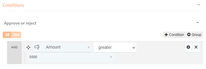
Fig. 620 Building the “If Amount > 5000” condition
Then you must add a group with “+Group”, two conditions inside it with its “+Condition” button and click “Any” (Fig. 621) to be able to fill the two conditions that are evaluated with the “OR” operator.
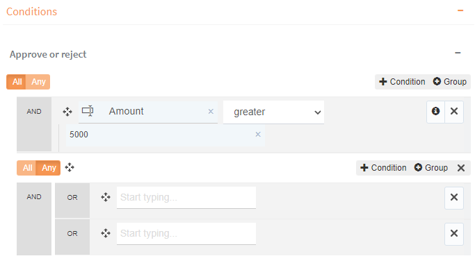
Fig. 621 Building a group with two conditions under the “OR” operator.
Once this is done you must complete the conditions’ fields: the first one, from left to right, with the “Product type” application datum, the “equals” operator and the value “1”. The second condition is completed in the same way but with the value “2” at the end, thus obtaining the final condition like Fig. 622 indicates.
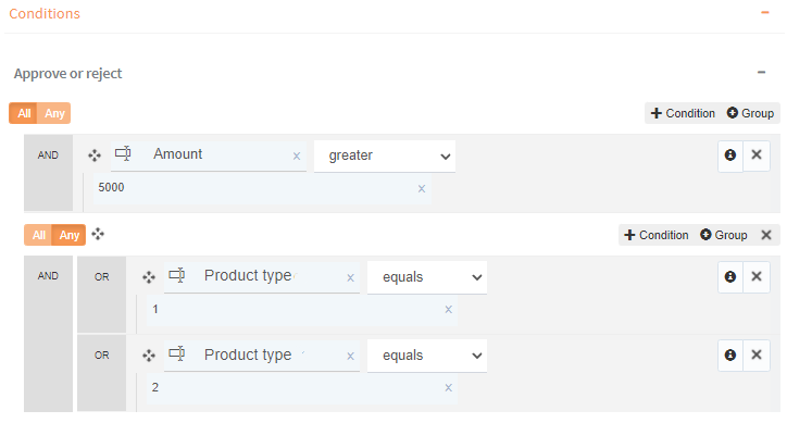
Fig. 622 “If Amount > 5000” and a group for “(Product type = 1 or Product type = 2)”
Convergent gateways properties
Parallel gateways and inclusive gateways are used in pairs. The second gateway has options to determine under which circumstances the flow must continue when it reaches it and what to do with any pending threads. These options are:
Continue after:
All threads have ended: the flow stops at the divergent gateway and waits for all threads to finish before continuing.
Some threads have ended: the flow will continue as soon as a certain number of threads have ended and will not wait for the other threads to finish. The number of threads to wait for is specified where it says “Number of threads”.
The threads coming from these steps have ended: it allows you to specify which threads the flow must wait for. The form shows the name of the last element of each thread along with a box that can be checked. The flow will continue when all the threads corresponding to the elements that have been checked are finished.
Finalize sibling threads: if this option is checked, all threads that have not finished will be finalized before the flow continues.
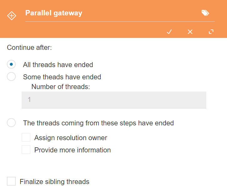
Fig. 623 Convergent gateways properties
Call activity
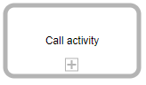
Fig. 624 Call activity
A call activity is used for a flow to start another flow, which is called “child flow” (the flow that started it is said to be its parent).
When a flow reaches a call activity, it starts a flow from the template indicated in the call activity’s configuration. Once the child flow has started, the parent flow can continue its execution without waiting for the child’s execution to end or it can stop and wait for its execution to end before continuing.
The properties form of a call activity is divided into two tabs:
General: it allows you to specify the template that will be used to start flows from the activity and some other flow properties.
Mappings: it allows you to specify correspondences between the parent flow’s application data and the child flow’s application data, and between the parent flow’s roles and the child flow’s roles. This allows the two flows to exchange information, by copying the value of data or roles of one of them to the data or roles corresponding to the other. You can also specify that attachments should be copied from one flow to the other.
General
Template: it specifies the process template to which the flows that are started from the call activity belong.
Version: it specifies which template version will be used to start the flows.
Use published version: check this option if you wish to always use the published version at the time of starting the child flow.
Template version: this option allows you to select a specific version.
Flow name: it is the name of the flow to start. A tag can be used so that the name is, for example, the value of an application datum. For more details, check the Tags section.
Flow description: a description of the flow to start. A tag can be used so that the description takes the value, for example, of an application datum. For more details, check the Tags section.
Wait for subflow end to continue: if this option is checked, once the child flow has started, the flow that created it will not continue its execution until the child has finished. The parent flow’s data can only be updated from the child flow if this option is checked.
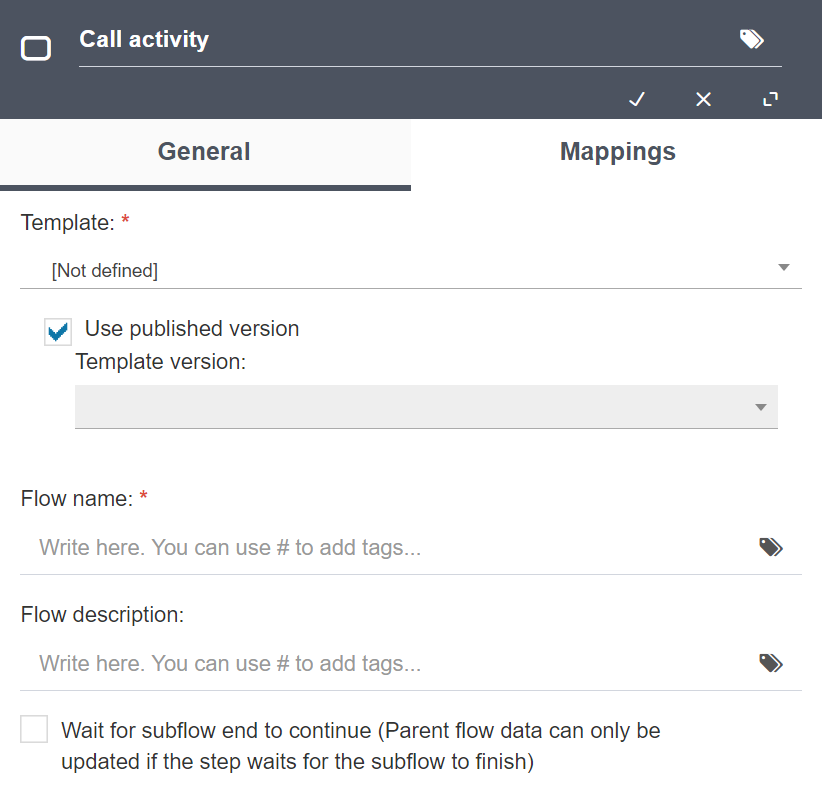
Fig. 625 Call activity properties, “Template”
Mappings
The mappings tab shows an initially empty table to which rows can be added. Each row represents a correspondence between a parent flow’s data or role and a child flow’s data or role. At the bottom are the attachment mapping options.
Above the table with the data and role correspondences are the buttons that allow you to add an applicationn data mapping, add a role mapping, and delete the selected mapping (Fig. 626). If the “Template” section’s options have not been filled yet, the buttons are disabled, given that it is impossible to know what application data and process roles are available in the flow that is started.
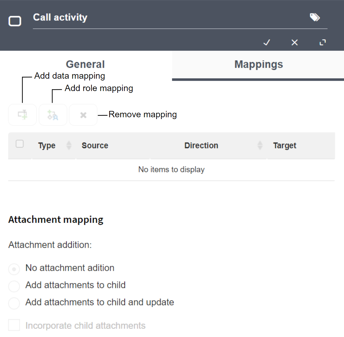
Fig. 626 Mappings
When you click one of the buttons that are used to add a mapping, a new row is added to the mappings table. To specify the mapping’s properties, click each cell of the new row and select the desired values.
A mapping has the following properties (each one corresponds to a table column):
Type: it indicates whether the mapping is of roles or data. This is determined by the button that was used to add the mapping and cannot be modified.
Source: the parent flow’s application datum or role.
Target: the child flow’s application datum or role.
Direction: it indicates if the value will be copied from the source datum or role to the target datum or role or viceversa:
Input: the value of the parent flow’s datum or role is copied to the child flow’s datum or role. This is done at the time of starting the flow.
Output: the value of the child flow’s datum or role is copied to the parent flow’s datum or role. This is done when the child flow finishes its execution and only if the parent flow waits for the child flow. If the parent flow continues its execution immediately after starting the child, without waiting for it to finish, no data or roles are copied from the child to the parent.
Input/Output: the value of the parent flow’s datum or role is copied to the child flow at the time of starting the child flow. Once the child flow’s execution has finished, if and only if the parent waited for the child to finish before continuing, the value of the child flow’s datum or role is copied to the parent flow’s datum or role.
IMPORTANT: for a datum or role to appear in the list that allows you to select them as a Target, they must be editable in the child flow’s start event. If a datum or role does not appear in the list of possible targets, check the visibility it has in the start event of the version that will be used to start the child flow.
In the form’s lower half are the options for attachment mappings:
No attachment addition: Qflow does not copy the parent flow’s attachments to the child flow.
Add attachments to child: when starting the child flow, Qflow copies the parent flow’s attachments to it.
Add attachments to child and update: when starting the child flow, Qflow copies the parent flow’s attachments to it. Once the child flow has finished its execution, if there were changes in those attachments, it copies them again to the flow that started it, but only if the parent waited for the child to finish before continuing.
Incorporate child attachments: if this option is checked, Qflow incorporates all the files that were attached to the child during its execution to the parent. This is only done if the parent waits for the child.
Subprocess
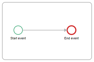
Fig. 627 Subprocess
A subprocess is an element that contains various elements and allows you to handle a part of the process design as if it were a unit. It is used to simplify the process design, since it can be contracted, so it is seen as a simple activity, or expanded, showing its entire content, which can be modified as if it were a process design inside the process design.
A recently created subprocess has a start event and an end event. When the flow reaches a subprocess execution, it starts at the start event and ends its execution when it reaches an end event.
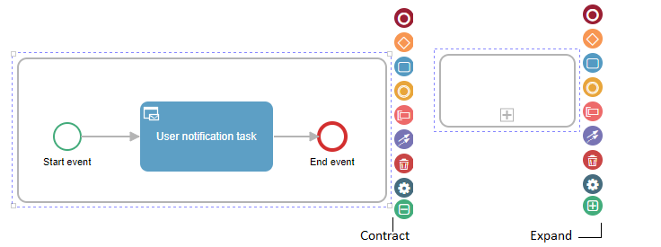
Fig. 628 Expanded (left) and contracted (right) subprocess, with the buttons that allow you to expand it and contract it
Script task
Fig. 629 Script task
A script task allows you to write a program for a flow to execute. The script can be written in the C# or Visual Basic .NET languages and must implement an interface that is defined in Qflow.
Script task properties
A script task, aside from the name and description, has the following properties:
Programming language: it allows you to select the programming language (C# or VB .NET).
Code: it is the script code.
The code contains a function named “Execute”. When a flow executes the code, it will call that function. The code is written inside a class derived from the CodeScriptBase class, which is defined by Qflow. That class has a set of methods and properties that allow you to work with the flow data. For more information on how to use those methods and properties, check the Scripting Interface manual.
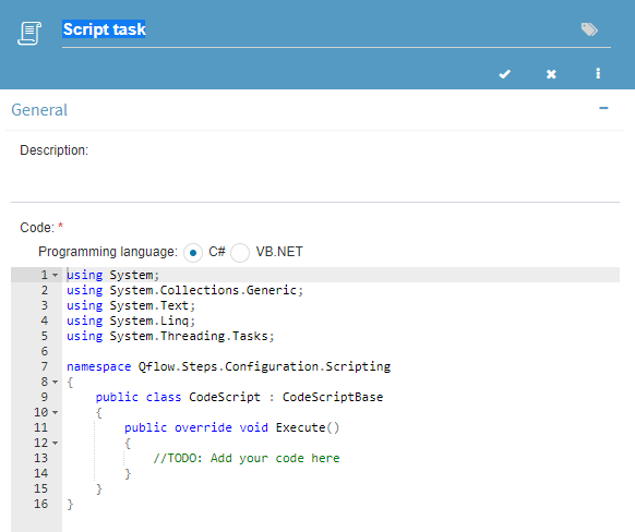
Fig. 630 Script task properties
Service task
Fig. 631 Service task
The service task is a type of step used to run a user-defined integration (see Integrations) or to use any of the predefined connectors that Qflow offers (see Connectors).
The service task configuration panel shows a wizard with steps to complete before being able to save the step.
The “Handled events” section allows assigning event handlers to various milestones in the task’s lifecycle, such as events for the start of the task, the end of the task, or events in the case of errors in the execution. For more information, see Associate a handler to a task event.
Read below for an explanation on how to configure both user integrations and connectors:
Integration configuration
On the first step of the wizard (Fig. 632) choose the first option from the list, “Integrations” and click on “Next”.
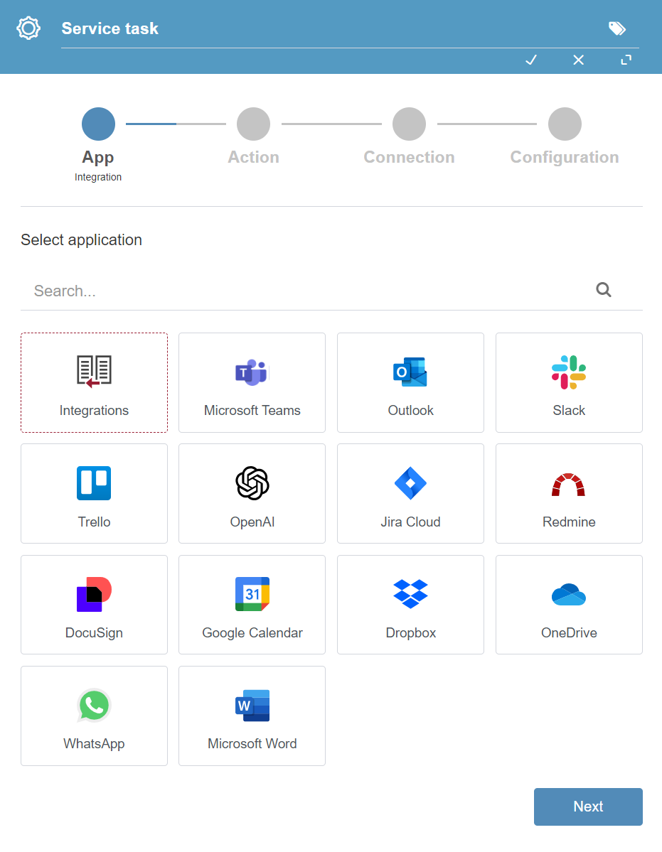
Fig. 632 Service task configuration panel
In this step (Fig. 633) a list is shown of all the integrations reachable for the version (that is to say, they must be defined in the version where the task is being configured, or in any template or package from which the version descends) that have a production operation defined (note that created integrations may not have a production operation defined, in which case it will not be shown in the list). Select the integration that you want to use and click on “Next”.
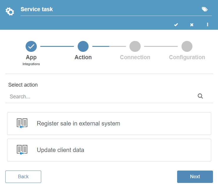
Fig. 633 User integrations list
The third step is where connection parameters are defined, which are not used in user-defined integrations, as such, it is not necessary to configure anything in this step, and you can continue by clicking on “Next”.
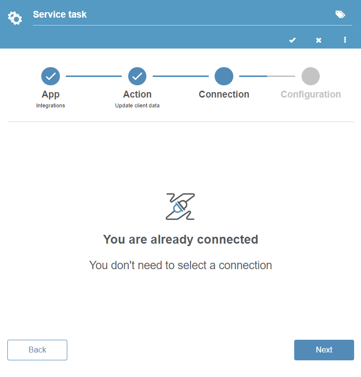
Fig. 634 Connection configuration for user integrations
The last step is to assign values to the integration’s parameters. In this step tabs will be shown that correspond to input, output and input/output parameters. On each tab, the parameters are shown with an input field and an icon that represents the parameter’s type.
We can assign application data (or text application parameters for input parameters) by starting to write in the fields, so that the site displays a list of available options. Click on the options to map them to the parameter.
The “Auto map” option automatically assigns all the application data to the parameters that have the same name.
It is necessary to map all required parameters (marked with a red asterisk) before continuing. Once the parameters have been mapped, click on “Finish” to complete the configuration.
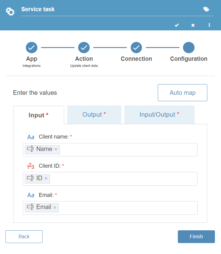
Fig. 635 Service task parameter mappings
Once you are done assigning the parameters, you can save the panel to finish with the service task’s configuration.
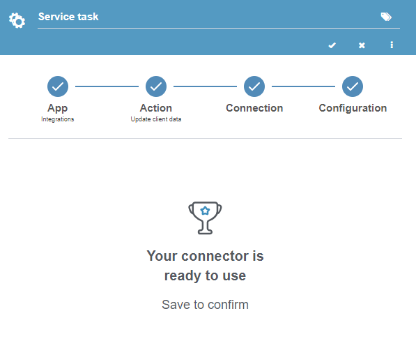
Fig. 636 Service task configuration finished
Connector configuration
To configure a connector, see the configuring connectors from a service task page.
Async service task
Fig. 637 Async service task
An async service task allows you to assign a job to a bot. A bot can have parameters, just like an integration. An async service task is very similar to a service task, the only difference being that, instead of selecting an integration to run, you select a bot (Fig. 638).
The async service task properties form includes two tabs:
General
Allows you to choose the bot to which the job will be assigned and map the input and/or output parameters.
Dev tools
Allows you to configure event handlers (see Associating a handler to a task event) and validations (see Associating a validation to a form).
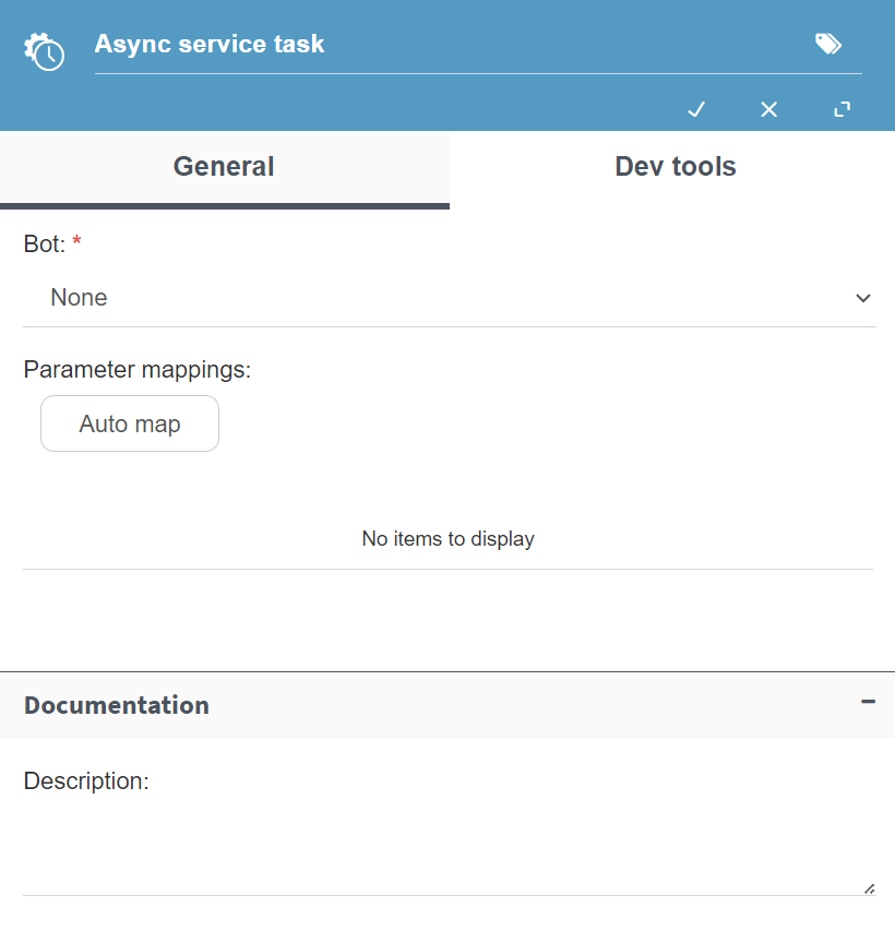
Fig. 638 Async service task properties
Intermediate events
They are those events that can occur between the start and end of a flow.
Timer event

Fig. 639 Timer event
A timer event allows you to specify a delay. When a flow reaches a timer event, it stops for the time specified in it. The timer event properties form allows you to specify how long the event should wait.
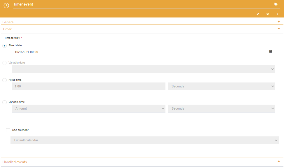
Fig. 640 Timer event properties
Simple intermediate event
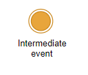
Fig. 641 Intermediate event
A simple intermediate event, which we will call intermediate event, allows you to mark a flow’s advance, by modifying the properties that have that purpose (progress, flag and stage).
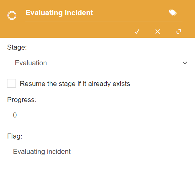
Fig. 642 Simple intermediate event properties
Catch signal event
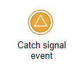
Fig. 643 Catch signal event
A catch signal event allows you to make the thread wait until a signal is received from a throw signal event. It is used in scenarios where it is necessary to synchronize the work of two or more threads that are executed simultaneously. The two properties specific to these events are the following:
Wait for signal from step: the throw signal step for which the step waits.
Continue if thrown: in case the signal was thrown before the attempt to catch it, this option specifies if the step should wait for a new signal or simply continue.
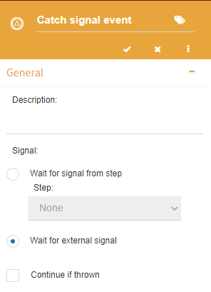
Fig. 644 Catch signal event properties
Throw signal event
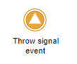
Fig. 645 Throw signal event
A throw signal event allows you to notify catch signal events that are waiting for it that they should continue their execution. This event’s configuration is similar to an intermediate event’s (see Simple intermediate event).
Intermediate boundary events
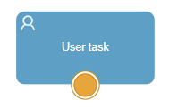
Fig. 646 Generic intermediate boundary event
Intermediate boundary events are events that can be attached to certain activities. If during the activity’s execution one of the defined events is triggered, the flow continues through a path that contemplates it. The events that Qflow admits as boundary events are:
Timer event: these events can be attached to user tasks or async service tasks, the flow will continue through this path when the time out defined in the activity itself occurs.
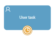
Fig. 647 Timer boundary event
Error event: these events can be attached to service tasks, script tasks, formula tasks and mail tasks. The flow will follow this path when an error occurs in the activity’s execution.
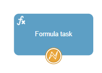
Fig. 648 Error boundary event
Artifacts
Artifacts are objects whose purpose is to make the process more manageable and comprehensible. In the process design, they have a different behavior from other elements: they are not part of the process flow. They can be connected to activities, events and gateways, but only to signal that they are related to them. They are informative elements that do not affect the process.
The available artifacts in Qflow are:
Data object reference: it represents a data set that is used in some activity.
Data store reference: it represents a data storage, for example a database.
Annotation: it allows you to write a text and associate it to some design element.
Data object and data store reference

Fig. 649 Data object reference

Fig. 650 Data store reference
Both a data object reference and a data store reference are added to the design and connected to the element to which they refer. For example, if a service task updates a database, a data store reference can be added to indicate the database that it updates (Fig. 651). To write the database name, double click the database reference. Under the object, a box will appear to type a text.
Another example: if a user uses a certain data set to perform a task, a data object can be included in the design to indicate what the data set is (Fig. 652).
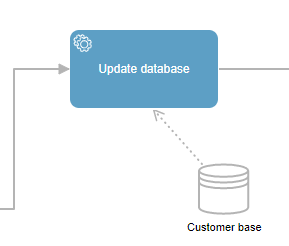
Fig. 651 Database reference in service task
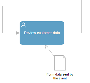
Fig. 652 Data object reference in user task
Annotation

Fig. 653 Annotation
When a process design element is selected, one of the options that appear is used to add an annotation. If you click the corresponding button, Qflow will create an annotation and allow you to place it where you wish. Once the annotation has been placed, double click it to enter a text. You can increase an annotation’s size to make the text fit.
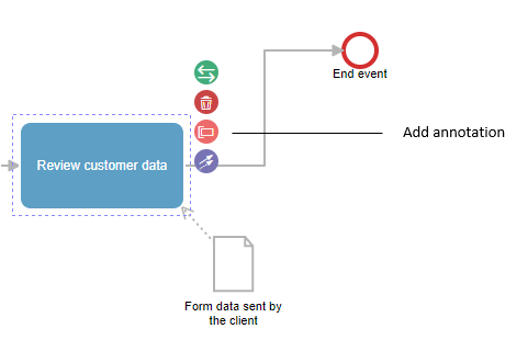
Fig. 654 Element options with the Add annotation button
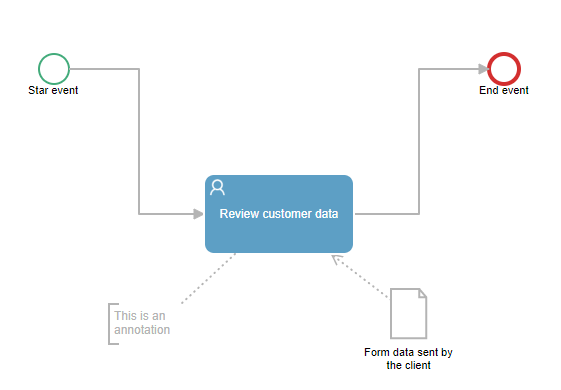
Fig. 655 Design with annotation
Pool
A pool allows you to create lanes to organize a process by grouping related elements inside the same pool.
When a pool is added, all the design elements are left inside of it. Dragging elements outside of the pool is not allowed: all design elements must be inside.
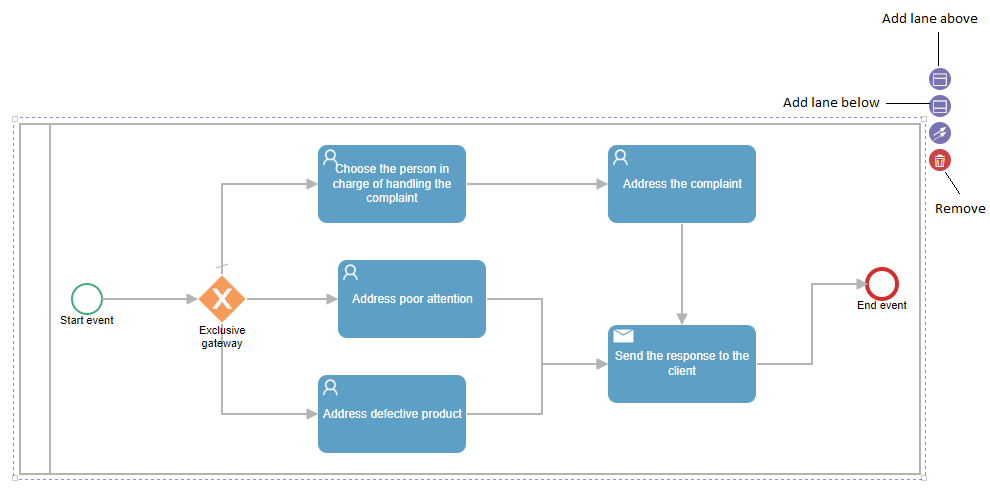
Fig. 656 Pool
Once a pool is created, more can be added with the buttons that appear when you select the pool (Fig. 656). The pools’ size can be increased or decreased, by selecting them and using the mouse to drag their borders to one side or the other.
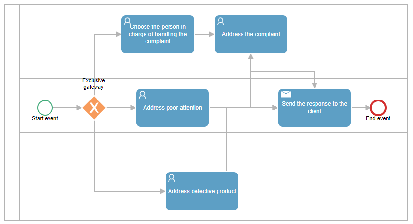
Fig. 657 Process with pools
Custom forms
Introduction
Custom forms let you visually define the structure and design of the forms used in one or more steps of the process. Their main function is to control the appearance, order, and organization of the fields shown to the user when completing a task.
You create these forms in the form designer: a graphical tool that makes it easy to build, visually, the interfaces that integrate into different stages of the process. Once created, the form can be associated with one or more steps (user tasks or start events), thereby determining when it will be shown during execution.
Unlike other data-entry mechanisms, a custom form does not change the process logic or its execution rules. Its purpose is solely to define how the information is presented, with which labels, and under what visibility conditions.
Each form can be adapted to different contexts through specific rules configured per field and per stage. This lets you, for example, show a set of data at the start and hide it or make it read-only in later phases.
Creating a custom form
To create a new custom form, select an existing process and choose a compatible element (such as a user task or a start event) to edit.
From the selected element:
Go to the properties panel.
In the Form section, select Create custom form.
Once created, the form is linked to the current version of the process.
The same form can be assigned to multiple elements (start event or user task) within the same process, but it cannot be reused in other processes.
Adding and configuring components in the form
The form designer lets you create forms easily. To get started, you just need to drag and drop components from the left panel into the central area of the screen. These components are organized into categories such as “Format and help,” “Data and roles,” or “Others.” When you add a data-type component, the system will ask you to provide a name, since it is required. That data item will be created in Qflow Design and will be available for reuse in other forms.
Depending on the component you choose, the designer will automatically create either a field bound to a data item (such as text, a list, or a checkbox) or a visual element (such as a separator or a container). These components do not contain information themselves; they define how the form will look. Once added, you can move them within the view to organize the form’s structure as needed.
Components allow you to:
Visually represent form fields that will then be available during execution (such as text, numbers, dates, or options).
Organize the layout structure, using elements such as titles, messages, or separators.
Each component includes a gear icon that opens its properties panel. There you configure visual and functional aspects such as the data name, domain, and visibility.
In the form designer, you add components from the left panel by dragging and dropping. Depending on the type, they can create a new data item in Design, reuse one already defined, or simply add visual elements without binding data.
Data-type components (Text, Number, Combo Box, etc.): When you drag one of these components onto the form, a new data item is created and associated with the corresponding domain. In that case, you are asked to define a name to identify the data item within the process. For more information on available domains, see the Domains section.
Role components: Let you load a role defined in the process and display it as a field in the form. This field can be used, for example, to assign a role dynamically to a user. Its visibility is configured in the same panel used for data, where you define whether the field will be visible, editable, required, or hidden. For more information, see the Process template roles section.
Existing data and roles: Using Select existing data or Select existing roles, you can insert elements already defined in Design. These elements inherit their previous configurations. Within the form, you can edit their properties, and any changes are also reflected in the design environment.
Note
If you change a data item’s domain in Design, the change is automatically applied to all forms that use that data item. This ensures consistency between the central definition and its representation in the form.
Visual and helper components
Title: Visual component that lets you separate and name sections within the form.
Message: Used to display informational text or instructions to the user.
Comments log: Forms let you configure comments associated with the process that the user can fill in when submitting a task. These comments are not part of the structured data, but they allow you to record relevant notes in the process log.
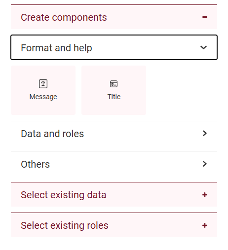
|
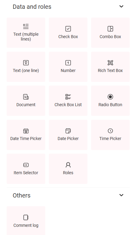
|
Note
Data defined in the template or in the version allows you to modify its settings within the form: name, domain, and visibility. Other data only lets you modify visibility (editable, required, read only, or hidden), but not its name or domain.
Form visibility and assignment:
The same form can be assigned to one or more elements of the process, provided they are a Start event or a User task. This assignment is done from Design, using the properties panel of the corresponding element.
Field visibility is configured exclusively in the form designer, where you define how each data item will appear in each process step: editable, required, read only, or hidden. For more information on these settings, see the Visibility of data, roles, attachments, and comments section.
Visibility |
Behavior |
|---|---|
Editable |
The field can be modified by the user. |
Required |
The field must be completed before proceeding. |
Read only |
The value is displayed but cannot be edited. |
Hidden |
The field is not shown in that step. |
Below the visibility assignment there is an additional control: the checkbox Allow value to be modified by code or dependency. This option determines whether the data can be updated automatically during process execution.
By dependencies: the value is calculated from other application data defined as domain parameters.
By code: the value can be modified in Code tasks by applying the logic configured in the process.
If the checkbox is not selected, the data value cannot be modified in code tasks or by dependencies, and will be limited to user interaction according to the configured visibility.
Example: in a leave request form, the End date field can be completed automatically as Start date + number of requested days. This calculation can be performed either by a dependency configured in the form or by a Code task, as long as the checkbox is selected.
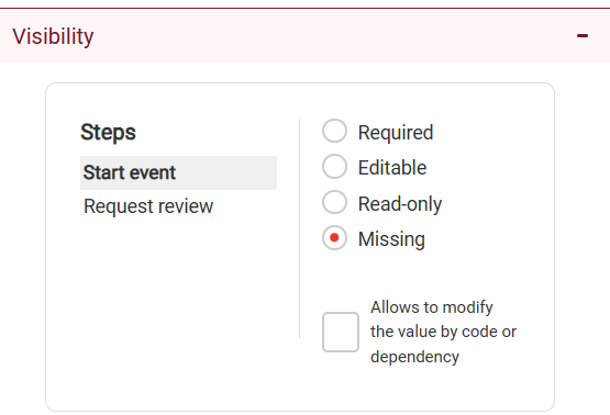
Preview and testing on devices
From the designer, you can open a preview of the form before publishing the process.
To open it:
Click Preview in the top-right corner.
The form will open in a new tab, showing its current structure.
The preview lets you review:
The visual distribution of components.
How the form will look during execution.
During the preview you can interact with components (for example, type text or select options), but these actions are not saved and do not affect the process.
Note
The preview does not evaluate validations, process logic, step-based visibility, or external integrations. It only represents the form’s general visual structure.
Testing on mobile devices with a QR code
Within the preview menu you will find the Scan QR option.
This feature generates a QR code that can be scanned from a mobile device or tablet to open the form. It lets you validate the design and the experience on smaller screens.
The form opens respecting the current configuration.
It does not record data or execute the process.
The QR link is valid for 30 minutes.
Note
This feature lets you validate the design on mobile or tablet environments. It cannot be used as a functional test of the flow.
Designer top bar
The top of the designer includes global access and controls:
Form name: identifies the current form.
“Preview” button: opens the visual simulation of the form.
QR menu: lets you generate a code to open the form on a mobile device.
Navigation (grid): direct access to Task, Admin, Design, and Team.
User menu: account and session settings.
All changes are saved automatically. For the form to be functional within the process, you need to publish the version to which it was assigned.
Note
Publishing the process version is required for the form to run in a real context.